- Kenmore refrigerator water filters
- Whirlpool refrigerator water filters
- Samsung refrigerator water filters
- GE refrigerator water filters
- LG refrigerator water filters
- Frigidaire refrigerator water filters
- KitchenAid refrigerator water filters
- Maytag refrigerator water filters
- Kenmore Elite refrigerator water filters
- Estate refrigerator water filters
- GE Profile refrigerator water filters
- Amana refrigerator water filters
- Bosch refrigerator water filters
- Dacor refrigerator water filters
- Electrolux refrigerator water filters
Top DIY repair help
View All Repair Categories
Appliances
Lawn & Garden
Power Tools
Home Improvement
Sports & Leisure
Heating & Cooling
Craftsman 113243300 band saw manual
Are you looking for information on using the Craftsman 113243300 band saw? This user manual contains important warranty, safety, and product feature information. View the user manual below for more details. Want a copy for yourself? Download or print a free copy of the user manual below.
BAND SAWSANDER (OWNERS)(viewing)Download PDF
![]()
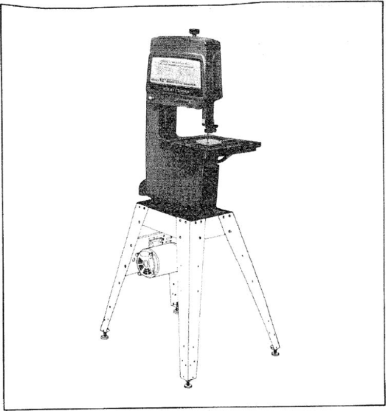
12-INCH BAND SAW/SANDER
- assembly
- operating
- repair parts
Save This Manual
For Future Reference
SEARS
owner manual
MODEL NO.
113.243300
SAW ONLY
MODEL NO.
113.243311
SAW WITH LEGS
AND MOTOR
Serial
Number_____________
Model and serial
number may be found
at the right-hand side
of the frame.
You should record both
model and serial number
in a safe place for
future use.
CAUTION:
Read GENERAL and
ADDITIONAL SAFETY
INSTRUCTIONS
carefully
Sold by SEARS, ROEBUCK AND CO., Chicago, IL. 60684 U.S.A.
FULL ONE YEAR WARRANTY ON CRAFTSMAN BAND SAW
If within one year from the date of purchase, this Craftsman Band Saw fails due to a defect in material or workmanship. Sears will repair it, free of charge.
WARRANTY SERVICE IS AVAILABLE BY SIMPLY CONTACTING THE NEAREST SEARS SERVICE CENTER/DEPARTMENT THROUGHOUT THE UNITED STATES.
THIS WARRANTY APPLIES ONLY WHILE THIS PRODUCT IS IN USE IN THE UNITED STATES.
This warranty gives you specific legal rights, and you may also have other rights which vary from state to state.
SEARS, ROEBUCK AND CO.. 698/731A, Sears Tower, Chicago, IL 60684
general safety instructions for power tools
KNOW YOUR POWER TOOL
Read and understand the owner's manual and labels affixed to the tool. Learn its application and limitations as well as the specific potential hazards peculiar to this tool.
GROUND ALL TOOLS
This tool is equipped with an approved 3 conductor cord and a 3-prong grounding type plug to fit the proper grounding type receptacle. The green conductor in the cord is the grounding wire. Never connect the green wire to a live terminal.
KEEP GUARDS IN PLACE
– in working order, and in proper adjustment and alignment.
REMOVE ADJUSTING KEYS AND WRENCHES
Form habit of checking to see that keys and adjusting wrenches are removed from tool before turning it on.
KEEP WORK AREA CLEAN
Cluttered areas and benches invite accidents. Floor must not be slippery due to wax or sawdust.
AVOID DANGEROUS ENVIRONMENT
Don't use power tools in damp or wet locations or expose them to rain. Keep work area well lighted. Provide adequate surrounding work space.
KEEP CHILDREN AWAY
All visitors should be kept a safe distance from work area.
MAKE WORKSHOP CHILD-PROOF
– with padlocks, master switches, or by removing starter keys.
DON'T FORCE TOOL
It will do the job better and safer at the rate for which it was designed.
USE RIGHT TOOL
Don't force tool or attachment to do a job it was not designed for.
WEAR PROPER APPAREL
Do not wear loose clothing, gloves, neckties or jewelry (rings, wristwatches) to get caught in moving parts. NONSLIP footwear is recommended. Wear protective hair covering to contain long hair. Roll long sleeves above the elbow.
USE SAFETY GOGGLES (Head Protection)
Wear safety goggles (must comply with ANSI Z87.1) at all times. "Everyday eyeglasses only have impact resistant lenses, they are NOT safety glasses." Also, use face or dust mask if cutting operation is dusty, and ear protectors (plugs or muffs) during extended periods of operation.
SECURE WORK
Use clamps or a vise to hold work when practical. It's safer than using your hand, frees both hands to operate tool.
DON'T OVERREACH
Keep proper footing and balance at all times.
MAINTAIN TOOLS WITH CARE
Keep tools sharp and clean for best and safest performance. Follow instructions for lubricating and changing accessories.
DISCONNECT TOOLS
before servicing; when changing accessories such as blades, bits, cutters, etc.
AVOID ACCIDENTAL STARTING
Make sure switch is in "OFF" position before plugging in.
USE RECOMMENDED ACCESSORIES
Consult the owner's manual for recommended accessories. Follow the instructions that accompany the accessories. The use of improper accessories may cause hazards.
NEVER STAND ON TOOL
Serious injury could occur if the tool is tipped or if the cutting tool is accidentally contacted.
Do not store materials above or near the tool such that it is necessary to stand on the tool to reach them.
CHECK DAMAGED PARTS
Before further use of the tool, a guard or other part that is damaged should be carefully checked to ensure that it will operate properly and perform its intended function. Check for alignment of moving parts, binding of moving parts, breakage of parts, mounting, and any other conditions that may affect its operation. A guard or other part that is damaged should be properly repaired or replaced.
DIRECTION OF FEED
Feed work into a blade or cutter against the direction of rotation of the blade or cutter only.
NEVER LEAVE TOOL RUNNING UNATTENDED
Turn power off. Don't leave tool until it comes to a complete stop.
additional safety instructions for band saw / sander
Safety is a combination of operator common sense and alertness at all times when the band saw is being used.
WARNING: FOR YOUR OWN SAFETY, DO NOT ATTEMPT TO OPERATE YOUR BAND SAW UNTIL IT IS COMPLETELY ASSEMBLED AND INSTALLED ACCORDING TO THE INSTRUCTIONS,.. AND UNTIL YOU HAVE READ AND UNDERSTOOD THE FOLLOWING:
PAGE
Stability of Machine
Your band saw must be bolted securely to a stand or work bench. In addition, if there is any tendency for the band saw to tip over or move during certain operations such as cutting long heavy boards, bolt your bandsaw to the floor.
Location
The band saw should be positioned so neither the operator nor a casual observer is forced to stand in line with the blade. This band saw is intended for indoor use only.
Protection: Eyes, Hands, Face, Ears, Body
Wear safety goggles that comply with ANSIZ87.1 and a face shield if operation is dusty. Wear ear plugs or muffs during extended periods of operation. Do not wear gloves... roll long sleeves above the elbow.
Do not cut pieces of material too small to hold by hand.
Avoid awkward hand positions where a sudden slip could cause a hand to move into the blade or the sanding belt.
Never turn your band saw "ON" before clearing the table of all Objects (tools, scraps of wood, etc.) except for the workpiece and related feed or support devices for the operation planned.
Make sure the blade runs downward toward the table in the right direction. Always adjust tracking wheel correctly so that the blade does not run off the wheels.
Always adjust tension correctly for the blade or sanding belt being used...
Always adjust the upper blade guide and blade guard to just clear the workpiece to protect the operator, to keep blade breakage to a minimum, and to provide maximum support for blade.
When cutting a large piece of material, make sure it is supported at table height.
Hold the work firmly against the table. DO NOT FREEHAND
Do not feed the material too fast while cutting. Only feed the material fast enough so that the blade will cut. Keep fingers away from the blade.
Use caution when cutting off material which is irregular in cross section which could pinch the blade before the cut is completed. A piece of molding for example must lay flat on the table and not be permitted to rock while being cut.
Use caution when cutting off round material such as dowel rods, or tubing. They have a tendency to roll while being cut causing the blade to "bite". Always use a "V" block, or clamp round material to a miter gauge.
When backing up the workpiece, the blade may bind in the kerf (cut )... this is usually caused by sawdust clogging up the kerf or because the blade comes out of the guides. If this happens:
- Turn off the band saw… remove plug from power source outlet… remove cover from band saw. insert a screwdriver or wedge in the kerf… rotate the wheels by hand while backing up the workpiece.
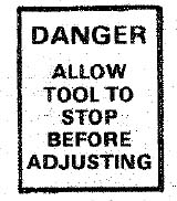
Never leave the band saw work area with the power on, before the machine has come to a complete stop, or without removing and storing the switch key.
Never operate the band saw with frame cover or with protective cover on the unused shaft end of the motor removed.
Do not perform layout, assembly, or setup work on the table while the cutting tool is rotating.
Turn saw "OFF" and remove plug from power before installing or removing an accessory or attachment.
Should any part of this band saw be missing, or bend, or fail in any way, or any electrical component fail to perform properly, shut off power switch, and remove power supply cord from power supply. Replace damaged, missing, and/or failed parts before resuming operation.
Think Safety.
Safety is a combination of operator common sense and alertness whenever the band saw/sander is in operation.
additional safety instructions for band saw / sander
WARNING: THE 5" BAND SAW PULLEY AND THE 2-1/2" MOTOR PULLEY FURNISHED, WILL RUN THE BLADE AT APPROXIMATELY 900 RPM (OR 2700 FEET PER MINUTE) WHEN USED WITH A 1725 RPM MOTOR. NEVER SUBSTITUTE THESE PULLEYS TO INCREASE THIS SPEED BECAUSE IT COULD BE DANGEROUS.
WARNING: DO NOT ALLOW FAMILIARITY (GAINED FROM FREQUENT USE OF YOUR BAND SAW) TO BECOME COMMONPLACE. ALWAYS REMEMBER THAT A CARELESS FRACTION OF A SECOND IS SUFFICIENT TO INFLICT SEVERE INJURY.

The operation of any power tool can result in foreign objects being thrown into the eyes, which can result in severe eye damage. Always wear safety goggles complying with ANSI Z87-1 (shown on Package) before commencing power tool operation. Safety Goggles are available at Sears retail or catalog stores.
READ AND FOLLOW THE INSTRUCTIONS APPEARING ON THE INSTRUCTION PLATE ON THE FRONT OF THE BAND SAW/SANDER AND FRONT OF THE BLADE GUARD.

motor specifications and electrical requirements
This machine is designed to use a 1725 RPM motor only. Do not use any motor that runs faster than 1725 RPM. It is wired for operation on 110-120 volts, 60 Hz., alternating current. (TOOL MUST NOT BE CONVERTED TO OPERATE ON 230 VOLT EVEN THOUGH SOME OF THE RECOMMENDED MOTORS ARE DUAL VOLTAGE. CHANGING TO 230 VOLT WILL NOT CONSERVE ENERGY AND REQUIRES CHANGING THE POWER CORD PLUG AND MOTOR RECEPTACLE.
THESE CRAFTSMAN MOTORS HAVE BEEN
FOUND TO BE ACCEPTABLE FOR USE ON
THIS TOOL.
| HP | RPM | VOLTS | CATALOG NO. |
|---|---|---|---|
| 1/2 | 1725 | 115 | 1278 |
| 1/2 | 1725 | 115 | 1279 |
| 1/2 | 1725 | 115 | 1289 |
CAUTION: Do not use blower or washing machine motor, or any motor with an automatic reset overload protector, as their use may be hazardous.
CONNECTING TO POWER SOURCE OUTLET
This machine must be grounded while in use to protect the operator from electric shock.
Plug power cord into a 110-120V properly grounded type outlet protected by a 15-amp dual element time delay or Circuit-Saver fuse or circuit breaker.
If you are not sure that your outlet is properly grounded, have it check by a qualified electrician.
WARNING: DO NOT PERMIT FINGERS TO TOUCH THE TERMINALS OF PLUGS WHEN INSTALLING OR REMOVING THE PLUG TO OR FROM THE OUTLET.
WARNING: IF NOT PROPERLY GROUNDED THIS POWER TOOL CAN CAUSE AN ELECTRICAL SHOCK PARTICULARLY WHEN USED IN DAMP LOCATIONS CLOSE TO PLUMBING. IF AN ELECTRICAL SHOCK OCCURS THERE IS THE POTENTIAl OF A SECONDARY HAZARD SUCH AS YOUR HANDS CONTACTING THE SAW BLADE.
If power cord is worn or cut, or damaged in any way, have it replaced immediately.
If your unit is for use on less than 150 volts it has a plug that looks like below.

This power tool is equipped with a 3-conductor cord and grounding type plug which has a grounding prong, approved by Underwriters' Laboratories and the Canadian Standards Association. The ground conductor has a green jacket and is attached to the tool housing at one end and to the ground prong in the attachment plug at the other end.
This plug requires a mating 3-conductor grounded type outlet as shown.
If the outlet you are planning to use for this power tool is of the two prong type DO NOT REMOVE OR ALTER THE GROUNDING PRONG IN ANY MANNER. Use an adapter as shown below and always connect the grounding lug to known ground.
It is recommended that you have a qualified electrician replace the TWO prong outlet with a properly grounded THREE prong outlet.
A temporary adapter as shown below is available for connecting plugs to 2-prong receptacles. The green grounding lug extending from the adapter must be connected to a permanent ground such as to a properly grounded outlet box.
A temporary adapter as illustrated is available for connecting plugs to 2-prong receptacles. The temporary adapter should be used only until a properly grounded outlet can be installed by a qualified electrician.
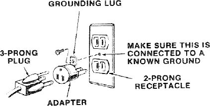
NOTE: The adapter illustrated is for use only if you already have a properly grounded 2-prong receptacle. Adapter is not allowed in Canada by the Canadian Electrical Code.
The use of any extension cord will cause some loss of power. To keep this to a minimum and to prevent over-heating and motor burn-out, use the table below to determine the minimum wire size (A.W.G.) extension cord. Use only 3 wire extension cords which have 3-prong grounding type plugs and 3-pole receptacles which accept the tools plug.
| Extension Cord Length | Wire Size A.W.G. |
|---|---|
| Up to 100 Ft. | 16 |
| 100. 200 Ft. | 14 |
| 200. 400 Ft. | 10 |
CHECK MOTOR ROTATION
Before checking motor rotation make sure key is removed from shaft. Place the motor on your workbench or on the floor. Standing clear of the shaft, plug the cord into a properly grounded outlet. Notice rotation of the shaft. If motor is not turning counterclockwise, remove the plug and contact your Sears store immediately. If motor turns counterclockwise remove the plug and proceed on with the assembly.
unpacking and checking contents
CONTENTS
- UNPACKING AND CHECKING CONTENTS ASSEMBLY
- GETTING TO KNOW YOUR BAND SAW/SANDER
- BASIC BAND SAW/SANDER OPERATION
- MAINTENANCE
- TROUBLE SHOOTING
- REPAIR PARTS
- MOTOR CONNECTIONS
Model 113.243300 Band Saw/Sander is shipped complete in one carton but DOES NOT INCLUDE Steel Legs or Motor.
Model 113.243311 Band Saw/Sander is shipped complete in one carton and INCLUDES Steel Legs and Motor.
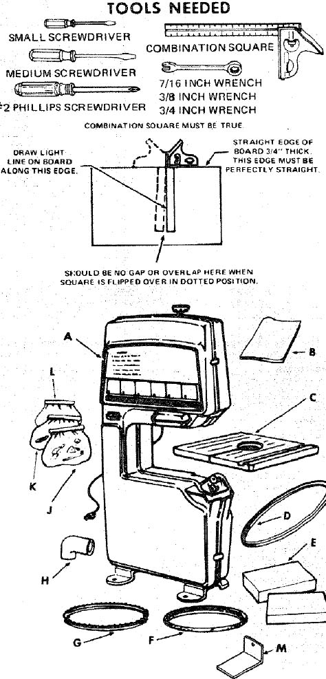
Separate all parts from packing materials and check each item with illustration and "Table of Loose Parts." Make certain all items are accounted for, before discarding any packing material.
If any parts are missing, do not attempt to assemble the band saw, plug in the power cord or turn the switch on until the missing parts are obtained and installed correctly.
| ITEM | TABLE OF LOOSE PARTS | QTY. |
|---|---|---|
| A | Basic Saw Assembly | 1 |
| B | Owner's Manual | 1 |
| C | Saw Table | 1 |
| D | 1/2 × 52-In. V-Belt | 1 |
| E | Carton containing Belt Guard, Belt-Guard Support, Support Bracket, three Clips and three Self-Tapping Screws | 2 |
| F | 1/2-In. Sanding Belt | 1 |
| G | 1/4-In Band Saw Blade | 1 |
| H | Sawdust Elbow | 1 |
| J | Loose Parts Bag #69139 | |
| (Containing the following items:) | ||
| Sanding Platen | 1 | |
| Wrench | 1 | |
| Table Insert | 1 | |
| Pulley, 5" | 1 | |
| Pulley Motor, 2-1/2'" | 1 | |
| Knob Tension Adj | 1 | |
| Tube Clamp | 1 | |
| Foam Gasket (Strip) | 1 | |
| K | Loose Parts Bag -#69140 | |
| (Containing the following items:) | ||
| Key, Sq. 3116 × 1-1/8" | 1 | |
| Wing Nut, 1/4-20 | 1 | |
| Spacer | 1 | |
| Screw. Truss Hd. 1/4-20 × 1 | 1 | |
| Hex, Nut 3/8-16 | 1 | |
| Flat Washer, 17/64 × 5/8 × 1/16 | 1 | |
| Flat Washer, .380 × 1-9/64 × 7/64 | 1 | |
| Set Screw Wrench, 1/8" | 1 | |
| Set Screw Wrench, 3/16" | 1 | |
| Set Screw Wrench, 5/32" | 1 | |
| L | Loose Parts Bag #69141 | |
| (Containing the following items:) | ||
| Switch Key | 1 | |
| Lockwasher, #6 | 1 | |
| Hex Nut, 6-32 | 1 | |
| Soc. Hd. Set Screw, 5/16-18 x 3/8" | 1 | |
| Screw, Pan Hd. Ty. "T" 8-32 x 3/8" | 2 | |
| Screw, Pan Hd. Ty. "T" 10-32 x 3/8" | 2 | |
| Screw, Flat Hd. 6-32 × 7/16" | 1 | |
| Cord Clamp | 1 | |
| Plate, Alignment | 1 | |
| Pointer | 1 | |
| M | "L" Bracket | 1 |
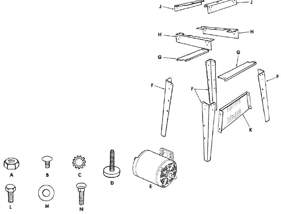
THE FOLLOWING PARTS ARE INCLUDED WITH MODEL 113.243311 ONLY.
| ITEM | Description | QTY. |
|---|---|---|
| A | *Nut, Hex Head 1/2-13 | 8 |
| A | * Nut, Hex 1/4-20 | 32 |
| B | * Screw Truss Hd. 1/4-20 × 5/8. | 32 |
| C | * Lockwasher, 1/4 External | 32 |
| D | * Foot, Leveling | 4 |
| E | Motor | 1 |
| F | Leg | 4 |
| G | Channel Support | 2 |
| H | Stiffener, Side | 2 |
| J | Stiffener, End | 2 |
| K | Support, Motor | 1 |
| HARDWARE FOR MOUNTING TOOL & MOTOR | ||
| L | * Screw, Hex Hd. 5/16-18 × 1 | 4 |
| C | * Lockwasher Ext. 5/16 | 8 |
| A | * Nut, Hex 5/16-18 | 8 |
| M | * Washer 11/32 D | 8 |
| N | * Bolt, Carriage 5/16-8 × 3/4 | 4 |
* parts Contained In Loose Parts Bag Part No. 69097
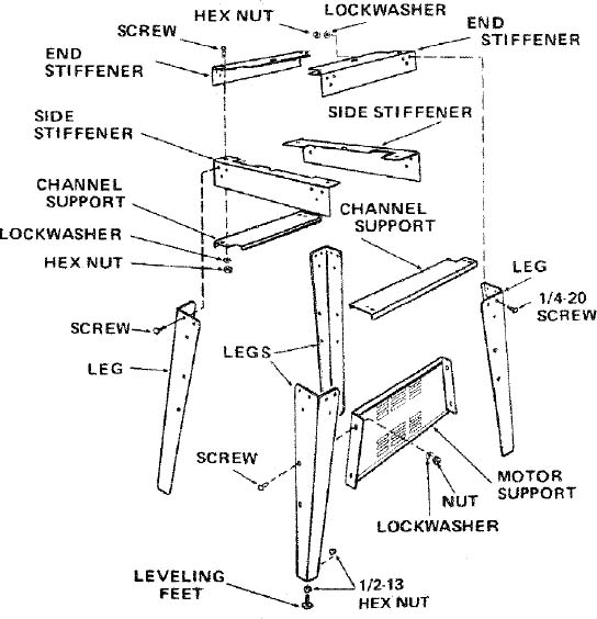
assembly
ASSEMBLING STEEL LEGS
Assemble the two (2) End Stiffeners and the two (2) Side Stiffeners using four (4) 1/4-20 Truss head screws. The End Stiffeners are placed on top of each Side Stiffener as shown. Insert screws through the 9/32 inch diameter holes and attach lockwashers and 1/4-20 nuts and finger tighten nuts.
Attach the four (4) legs to the Side and end Stiffeners using 1/4-20 screws, lockwashers and nuts as shown.
Remove the four (4) Truss head screws which were assembled in Paragraph No. One. Place the two (2) Support Channels as shown, in position, align holes in supports with holes in the Stiffeners, replace lockwashers and nuts. Tighten all nuts using 7/16" wrench.
Assemble the motor support to steel legs with 1/4-20 screws and nuts. Motor support can be mounted to either end of stand. Tighten nuts.
Install leveling feet as shown. To level Leg Set, loosen nut on inside of leg and turn nut on outside to raise or lower feet. Adjust all four levelers, if necessary, and then tighten nuts on inside of leg.
NOTE: These levelers are not intended for height adjustment.
MOUNTING BAND SAW/SANDER ON LEG SET
NOTE: For illustrative purposes, the Band Saw is shown mounted on the Craftsman Catalog No. 9-22236 Steel *Leg Set. This Leg Set is included with Model No. 113.243311.
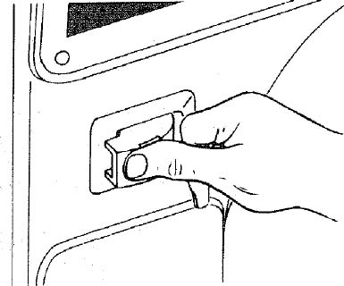
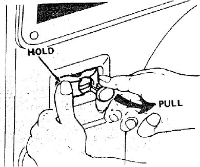
Remove the Band Saw cover by applying gentle side pressure on the spring tabs and release the top portion of the cover by pulling it away from the frame. Repeat procedure for bottom portion of cover.
NOTE: Check the bolts which hold the feet to the Band Saw as shown. Make sure they are tight.
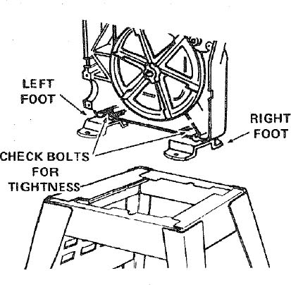
- Place the Band Saw on the Steel Legs, position as shown and align the mounting holes in the feet of the Band Saw with those in the END STIFFENERS (marked with an X in the illustration).
- Mount saw to legs using four (4)5/16-18×1" hex head screws, lockwashers, and hex nuts. Tighten screws.
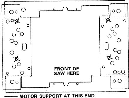
INSTALLING MOTOR, PULLEY, V-BELT, AND BELT GUARDS
- Locate the following parts:
| Qty. | Description |
|---|---|
| 1 | Motor |
| 1 | "L" Bracket |
| 1 | Small Pulley (approx. 2-1/2" Dia.) |
| 1 | Large Pulley (approx. 5" Dia.) |
| 1 | Woodruff Key 3/16" |
| 1 | V-Belt 1/2 × 52 |
| 1 | Motor Cord Clamp |
| 4 | Carriage Bolt 5/16-18 × 3/4 |
| 4 | Flat Washer 5/16 I.D. |
| 4 | Lockwasher 5/16 I.D. |
| 4 | Hex Nut 5/16-18 |
| 2 | Guard Assembly including a guard support, guard support bracket, self-threading screws, and clips. |
- Fasten a belt guard support to the band saw frame with self-threading screws.
- Install clips onto the guard support with long end facing you.
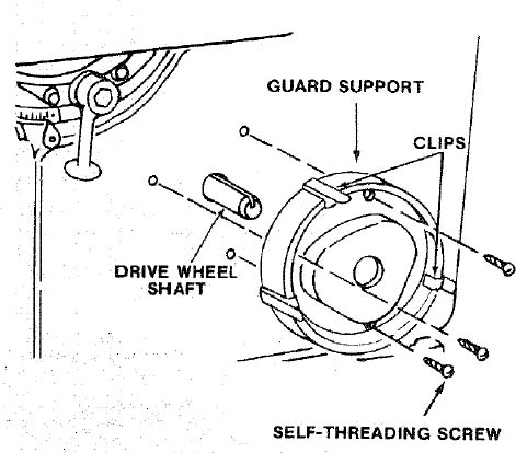
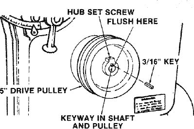
- Place the large pulley onto the drive wheel shaft and insert the key into the keyway of the shaft and pulley. Position pulley hub flush with end of shaft and tighten set screw securely against key.
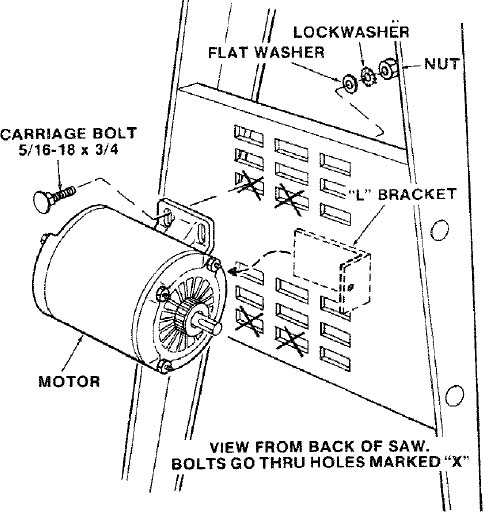
- Place motor against the motor mounting bracket and insert bolts through holes in motor base and then through holes marked "X" in motor mounting bracket. DO NOT TIGHTEN BOLTS AT THIS TIME. The "L" bracket which holds the guard support must be slid between the motor base and the motor mounting bracket so motor must be loosely assembled to bracket at this time.
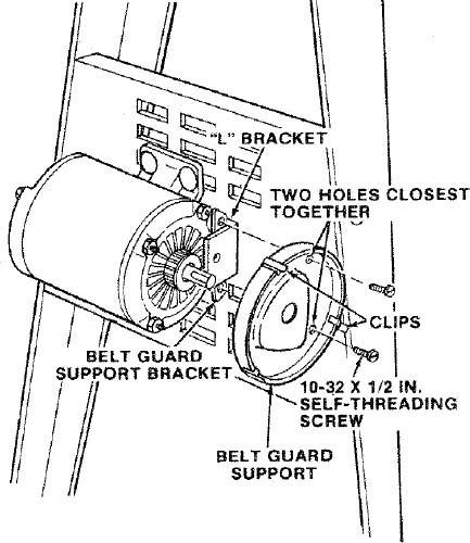
- Slide long leg of "L" bracket between motor base and motor mounting bracket. Then sandwich the "L" bracket between the guard support bracket and the guard support and loosely fasten together with self-threading screws as shown. Install clips onto belt guard support.
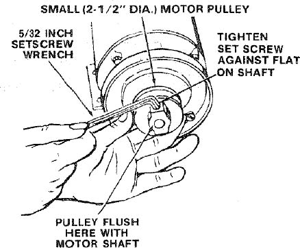
- Install the small pulley onto the motor shaft and tighten the set screw in the pulley hub against the flat part of the motor shaft.
- Push V-Belt partly through belt guard enough to allow belt to loop around the large pulley and push guard over belt and pulley into position on guard support.
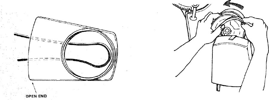
- Push the lower section of the V-Belt through the other guard as in the previous step and loop V-Belt around small pulley on motor shaft.
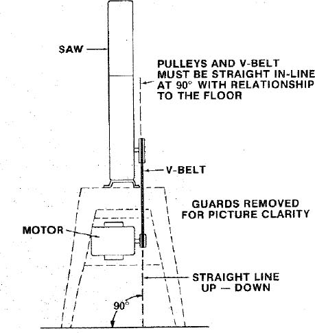
- Visually line up both pulleys and V-Belt until they are perpendicular to the floor by sliding motor sideways as needed.
- Press down hard on motor to put tension on the V-Belt and tighten the motor mounting bolts at this time.
- Check guard support before tightening guard support screws to be sure it is centered around motor shaft and will not rub against shaft when motor is running. Tighten screws.
- Push motor pulley belt guard into position onto guard support.
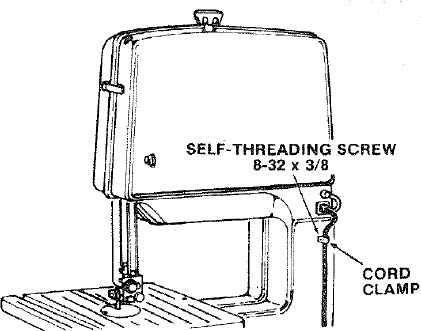
Route motor cord up and around front leg and along backside of saw frame.
Plug motor cord into outlet on upper section of band saw frame and secure cord with the cord clamp and screw.
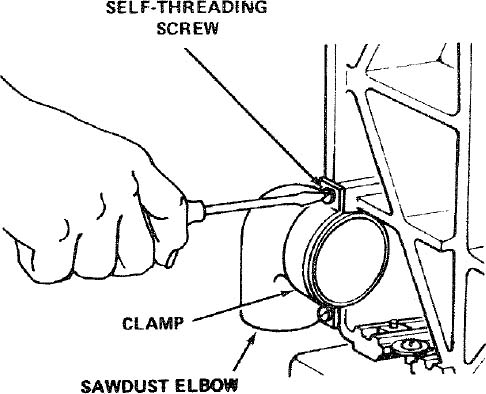
INSTALLING SAWDUST ELBOW
- Remove the Band Saw cover by applying gentle side pressure on the spring tabs and release the top portion of the cover by pulling it away from the frame. Repeat procedure for bottom portion of cover.
- Find the sawdust elbow, the clamp, the strip of rubber gasket, and two 10-32 × 3/8" self-threading screws among the loose parts.
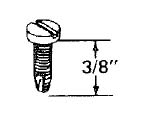
- Place the elbow in the opening at the bottom left-hand side of saw as shown, and attach the clamp with the two screws.
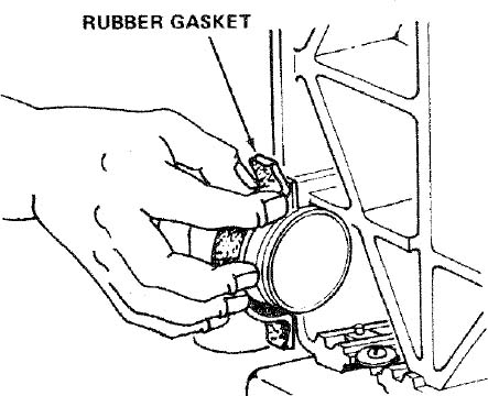
Peel off the protective covering from the rubber gasket and stick it around the clamp. Make sure it extends a little beyond each end of the clamp.
The gasket will help to prevent sawdust from leaking out.
For the most efficient removal of sawdust, attach a Craftsman Vac to the sawdust elbow.
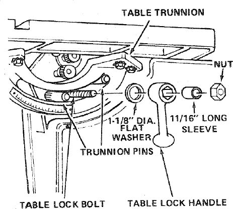
INSTALLING TABLE
Apply a coat of automobile wax to the table.
- Place the table on the band saw so that the two trunnion pins and the table lock bolt go through the slot in the trunnion.
- Find the 1-1/8" dia. flat washer, a sleeve 11/16" long, the trunnion lock nut and the table lock handle from among the loose parts.
- Hold the head of the table lock bolt inside the band saw with your left hand and put the 1-1/8" dia. flat washer, the sleeve, and the handle on the bolt.
- Screw the nut on the bolt and tighten it with the handle while the table is in a horizontal position.
INSTALLING THE BLADE
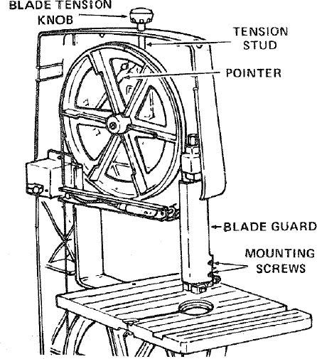
- Find the blade tension knob among the loose parts. Put a dab of grease or vaseline on the end of the knob and screw it on the tension stud. Screw it on only a few turns, just enough to start moving the pointer.
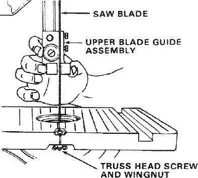
- Loosen the two mounting screws and remove the blade guard.
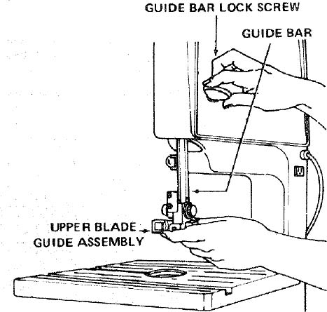
- Loosen the guide bar lock screw and position the upper guide assembly approximately three inches above the table as shown and tighten the lock screw.
Loosen the two setscrews which lock the upper blade guides and separate them about 1/8".
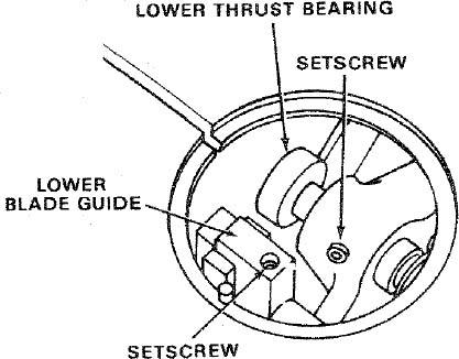
Do that same thing to the lower guides beneath the table. See Step 6 for location of setscrew.
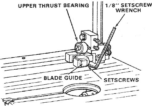
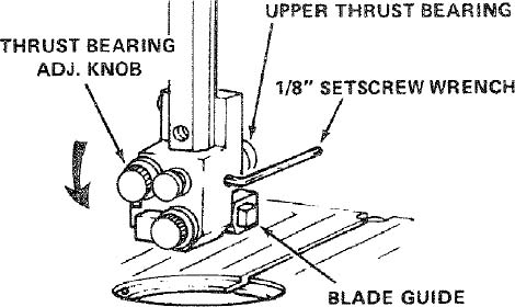
- Loosen the setscrew which locks the upper thrust bearing and turn the knob until the thrust bearing is all the way back as shown.
- Loosen the setscrew which locks the lower thrust bearing and turn the knob until the thrust bearing is all the way back.
TO AVOID BEING SCRAPED SHOULD BLADE SUDDENLY UNCOIL WEAR SAFETY GOGGLES AND CAREFULLY UNCOIL THE BLADE HOLDING IT AT ARMS LENGTH.
Carefully uncoil the blade, holding it at arms length.
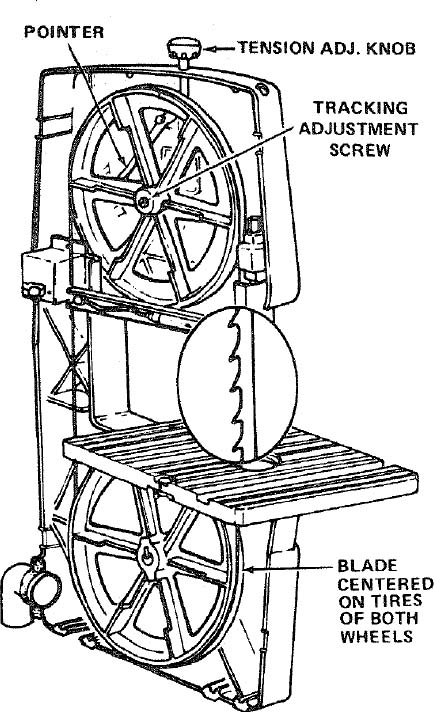
Place the blade over the wheels with the teeth pointing downwards toward the table as shown. Make sure the blade is between the blade guides and is in the center of the rubber tires.
NOTE: Your bandsaw can be used with blades of various widths from 1/8" to 1/2". The saw must be adjusted to the proper blade tension setting for the blade to be used. A 1/4" wide blade is included with this saw.
Screw down the tension knob until the pointer points to 1/4. This will put sufficient tension on a 1/4" wide blade.
Turn the upper wheel by hand a few times and notice if the blade remains in the approx. center of the tire on the top wheel.
If the blade moves away from the center of the wheel while you are turning it, the blade is not TRACKING properly.
The top wheel shaft is hinged which allows the wheel to be tilted so that the blade can be TRACKED. By turning the tracking adjustment screw, the wheel will be tilted. (see illustration).
If the blade moves toward the front of the band saw:
- Turn the tracking adjustment screw clockwise about 1/4 of a turn, as though you were tightening it.
If the blade moves toward the back of the band saw:
- Turn the tracking adjustment screw counterclockwise about 1/4 of a turn as though you were loosening it.
Turn the screw just enough to cause the blade to run in the approximate center of the tire.
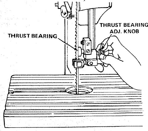
The thrust bearings support the blade from the rear and will rotate when the blade is pushed against them while you are cutting. As soon as you stop cutting, the bearings should stop rotating.
- To be sure the thrust bearing is properly supporting the blade, turn the thrust bearing adjustment knob so that the bearing moves toward the blade and almost touches it.
- While turning the upper wheel to the right by hand, adjust the thrust bearing until it barely touches the blade and starts to rotate. Now move the bearing back slightly, until it stops rotating. Tighten the thrust bearing setscrew.
- Adjust the lower thrust bearing the same way.
NOTE : The upper and lower blade guides support the blade and keep it from twisting during operation. An adjustment is necessary when blades are changed or replaced.
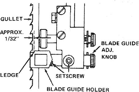
- To adjust the upper blade guides loosen the setscrew which locks the blade guide holder (see illustration ).
- Turn the blade guide adjustment knob, so that the guides move toward the blade. Move them until the "ledge" is about 1/32" from the deepest part of the blade teeth. This deep part is called a "gullet". Tighten the setscrew.
- Adjust the lower guides the same way.
- Press the two guides evenly against the sides of the blade, but don't pinch the blade. Release the guides and rotate the upper wheel a little bit, moving the blade downward. Make sure one guide is not farther away from the blade than the other. Tighten both setscrews.
- Adjust the lower guides the same way.
- Rotate the upper wheel a few times by hand, and check the guides and thrust bearings. Make readjustments if necessary.
- Replace the blade guard on the upper guide support.
- Locate the table insert and place it in the opening in the table.
- Replace the cover.
ADJUSTING THE TABLE
- Find a 1/4-20 × 1 inch truss head screw, a regular washer, and a 1/4-20 wing nut among loose parts. Insert the screw into the hole in the table top.
- From the underside of the table, screw the washer and wing nut onto the truss head screw and tighten finger tight. This will keep the table flat and in alignment.
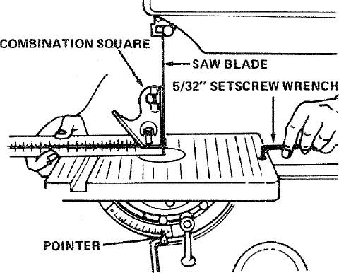
- Locate among the loose parts a 5/16"-18 x 3/8" socket head flat point setscrew.
- This setscrew acts as a 90° stop. Screw it partially into the tapped hole in the top of the table on the left side. Use the 5/32" setscrew wrench.
- Raise the blade guides all the way up.
- Loosen the table lock slightly and push down on the left side of the table until it touches the frame of the band saw.
- Screw in the stop screw and notice that as it touches the frame, the table will start to tilt.
- Place a square on the table against the blade and continue to screw in the stop screw until the table is square with the blade. Tighten the table lock.
"NOTE: The combination square must be "true" – see start of "assembly" section on pg. 6 for checking method."
NOTE: If the plastic housing should interfere with the underside of the table so that the table will not level, loosen the 4 bolts that hold the trunnion (see page 8) to the table and slide the table toward the rear of the saw. Tighten the bolts. The table should now adjust to a level position.
- Find the pointer and a pan head thread cutting screw 8-32 × 3/8 inches long and attach the pointer. Set it at 0 degrees and tighten the screw.
ON-OFF SWITCH
WARNING: DON'T CONNECT POWER CORD TO ELECTRICAL OUTLET IN YOUR SHOP UNTIL YOU ARE SURE THAT MOTOR ROTATION IS CORRECT, (SEE PAGE 5).
The On-Off Switch has a locking feature. THIS FEATURE IS INTENDED TO PREVENT UNAUTHORIZED AND POSSIBLY HAZARDOUS USE BY CHILDREN AND OTHERS.
- Insert key into switch.
NOTE: Key is made of yellow plastic

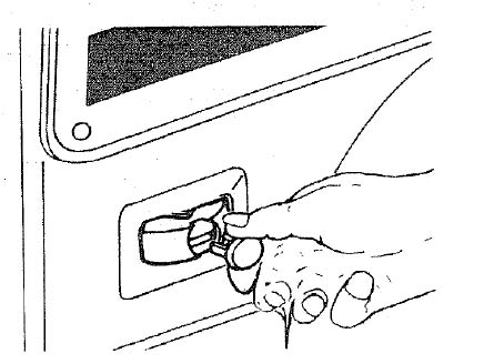
- To turn machine on, insert finger under switch lever and pull end of switch out.
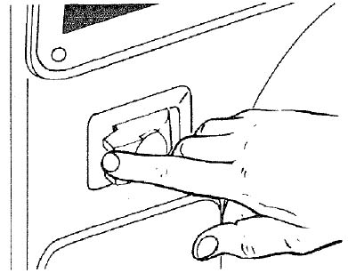
To turn machine OFF… PUSH lever in.
Never leave the machine unattended until it has come to a complete stop. Remove key and store remote from band saw.
- To lock switch in OFF position… hold switch IN with one hand… REMOVE key with other hand.
WARNING : FOR YOUR OWN SAFETY, ALWAYS LOCK THE SWITCH "OFF" WHEN MACHINE IS NOT IN USE… REMOVE KEY AND KEEP IT IN A SAFE PLACE… ALSO… IN THE EVENT OF A POWER FAILURE (ALL OF YOUR LIGHTS GO OUT) TURN SWITCH OFF… REMOVE THE KEY. THIS WILL PREVENT THE MACHINE FROM STARTING UP AGAIN WHEN THE POWER COMES BACK ON.
getting to know your band saw/sander
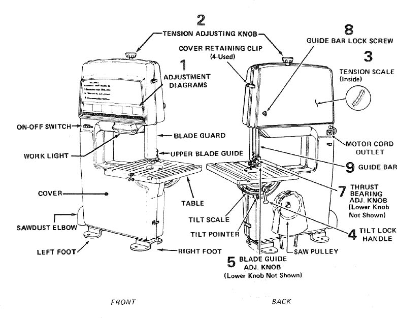
1. ADJUSTMENT DIAGRAMS
. . . Help you to become familiar with the adjustments.
2. TENSION ADJUSTMENT KNOB
. . . Tightening the knob will increase the tension on the blade. Loosening it will decrease the tension.
3. TENSION SCALES
. . . The fractional markings indicate the correct blade tension for various widths of blades. For example, when installing a 1/4" wide blade, tighten the tension knob until the pointer is pointing to the 1/4 marking.
4. TABLE TILTING
. . . Loosen the table lock handle, tilt the table to the desired angle and tighten the lock handle. To return the table to the 90° position, tilt it until the 90° stop screw rests on the frame, then tighten the lock handle.
5. BLADE GUIDE ADJUSTMENT
. . . Turning the knob moves the guides in or out for various widths of blades.
6. LATERAL BLADE GUIDE ADJUSTMENT
. . . . The guides can be adjusted sideways and locked in position by the setscrews.
7. BLADE THRUST BEARING ADJUSTMENT
. . . Turning the knob moves the thrust bearings in or out for various widths of blades.
8. GUIDE BAR LOCK SCREW
. . . The upper blade guides should just clear the workpiece while cutting. Always adjust the guides before turning on the band saw and lock the guide bar by tightening the thumb screw.
9. GUIDE BAR
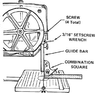
When the upper guides are raised or lowered, they must not deflect the blade sideways. This means that the guide bar must be parallel to the blade, or square with the table.
- Remove the blade guard, cover, blade, and the upper guide assembly.
- Lower the guide bar until the end is approximately 1-3/4" from the table.
- Hold a square on the table against the guide bar.
- If the bar is not square with the table, lock the guide bar and loosen the four screws in the guide bar support with a 3/16" setscrew wrench. To reach the lower left screw, it will be necessary to tilt the upper wheel outward.
NOTE: The holes in the guide bar support are larger than the screws. This allows the support to be moved.
- Move the guide bar until it is square with the table, then tighten the screws.
- Be sure to replace the blade guard before operation.
INSTALLING SANDING ATTACHMENT
WARNING: FOR YOUR OWN SAFETY, TURN SWITCH "OFF" AND ALWAYS REMOVE PLUG FROM POWER SOURCE OUTLET BEFORE INSTALLING SANDING ATTACHMENT.
- Remove the blade guard, the table insert, and the table alignment screw.
- Remove the cover, release the blade tension and remove the blade.
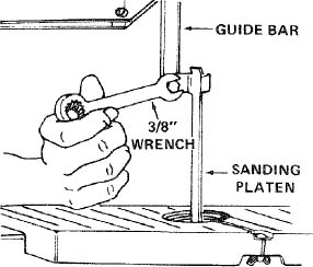
- Remove the upper blade guide assembly. Use a 7/16" wrench to remove the screw.
- Loosen the setscrew that locks the lower thrust bearing, and move the bearing as far back as it will go. Retighten setscrew.
- Loosen the two setscrews that lock the lower blade guides. Spread them apart so that the end of each guide is inside the holder. Retighten setscrew.
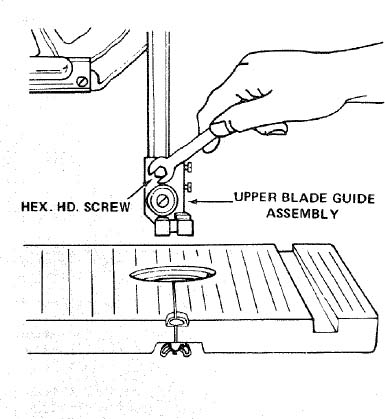
Attach the sanding platen to the guide bar with the same screw that held the upper blade guide assembly. Do not tighten the screw at this time.
On the smooth side of the sanding belt, you will find a "directional arrow". The belt must run in the direction of this arrow so that the splice does not come apart.
Place the belt on the wheels and tighten the tension knob until the pointer points to SAND. Rotate the upper wheel by hand a few times to make sure that the belt is tracking properly and is not rubbing the guides.
Loosen the guide bar lock screw and lower the end of the sanding platen below the table.
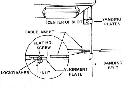
- Locate among the loose parts, the alignment plate, a flat head machine screw 6-32 x 7/16", a small hex nut and lockwasher.
- Attach the alignment plate to the insert so that the end of the alignment plate is in the center of the slot in the insert. Place the insert in the opening in the table.
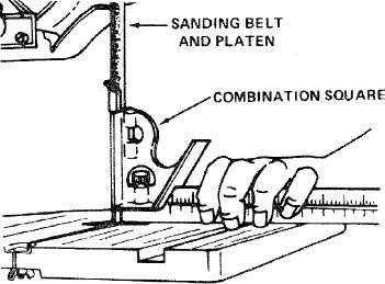
- Hold a square on the table against the sanding belt and platen.
- Tighten the hex. head screw which holds the platen to the guide bar.
- Replace the cover.
WARNING: FOR YOUR OWN SAFETY, DO NOT SAND IRON OR STEEL BECAUSE THE SPARKS COULD IGNITE THE SAWDUST INSIDE YOUR BAND SAW.
basic band saw/sander operation
BASIC BAND SAW/SANDER OPERATION
A band saw is basically a "curve cutting" machine. It is not capable of doing inside cutting.
Your Craftsman Band Saw/Sander is not only capable of the usual band saw operations, but it can be converted into a sander as well. You can finish wood, certain compositions and plastics and non-ferrous metals.
It is also used for straight-line cutting operations such as crosscutting, ripping, mitering, beveling, compound cutting, and resawing.
SAWING
WARNING: ADJUST THE UPPER GUIDES TO CLEAR THE WORKPIECE.
- Use both hands while feeding the work into the blade. Hold the workpiece firmly against the table. Use gentle pressure, and do not force the work, but allow the blade to cut.
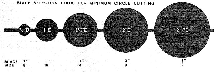
- The smallest diameter that can be cut out is determined by the width of the blade. For example, a 1/4" wide blade will cut a minimum diameter of approximately 1-1/2". (See Chart)
SANDING
The sanding belt cuts very rapidly. Practice with some scraps of wood first before you attempt to sand your actual workpiece.
- Press the workpiece gently against the sanding belt, and keep moving it until the edge is smooth.
maintenance
WARNING: FOR YOUR OWN SAFETY, TURN SWITCH "OFF" AND REMOVE PLUG FROM POWER SOURCE OUTLET BEFORE MAINTAINING OR LUBRICATING YOUR BAND SAW.
GENERAL MAINTENANCE
Pitch and sawdust that accumulate on the tires should be removed with a stiff brush or scraped off with a piece of wood. Do not use a sharp knife or any kind of solvent.
When the tires become worn they should be replaced. When replacing the tires, stretch them around the wheels but do not glue them onto the wheels.
Do not allow pitch to accumulate on the table, the insert, the guides or the thrust bearings. Clean them with Craftsman Gum and Pitch Remover. CAUTION: Do not immerse the thrust bearings.
Apply a thin coat of automobile-type wax on the table so that the wood slides easily while cutting.
MOTOR MAINTENANCE AND LUBRICATION
The bearings, in both end shields of the motor, have been lubricated at the factory with correct lubricant. No other part of the motor requires lubrication.
Re-lubricate motor bearings in accordance with the instructions on the nameplate. Be sure to wipe off dirt or grit if present around oil hole caps to prevent any possibility of foreign material contaminating the oil wicks that supply the bearings with oil. Use a good grade of medium weight mineral oil, such as automobile engine oil, SAE 20.
If disassembly of the motor is necessary, it should be returned to your nearest Sears retail or mail-order store in order to prevent voiding the guarantee.
NOTE: The speed of this motor cannot be regulated o changed.
Every effort should be made to prevent foreign materia from entering the motor. When operated under condition likely to permit accumulations of dust, dirt, or waste within the motor, a visual inspection should be made at frequen intervals. Accumulations of dry dust can usually be blow out successfully.
NOTE: Motors used on wood-working tools are particular susceptible to the accumulation of sawdust and wood chip and should be blown out or "vacuumed" frequently to prevent interference with normal motor ventilation and proper operation of the centrifugally-operated starting switch.
RECOMMENDED ACCESSORIES
| Item | Cat. No. |
|---|---|
| Floor Stand...................................... | 9-22213 |
| Steel Leg Set................................... | 9-22236 |
| Caster Set........................................ | 9-22222, 9-22221 |
| Miter Gauge................. | 9-29929 |
| Hold-Down Clamp for Miter Gauge.......................... | 9-29928 |
| Stop-Rods for Miter Gauge....................... | 9-29924 |
| Rip Fence.................... | 9-23433 |
| Blades and Sanding Belts........................ | See Catalog |
| Circle Cutting Attachment.................... | 9-24301 |
| Table Extension................................... | 9-24302 |
| Speed Reducer............................ | 9-23896 |
| Power Tool Know How Handbooks.................................. | |
| Radial Saw................................... | 9-2917 |
| Table Saw................................... | 9-2918 |
The above recommended accessories are current and were available at the time this manual was printed.
trouble shooting
WARNING: FOR YOUR OWN SAFETY, TURN SWITCH "OFF" AND REMOVE PLUG FROM POWER SOURCE OUTLET BEFORE TROUBLE SHOOTING YOUR BAND SAW/SANDER.
| TROUBLE | PROBABLE CAUSE | REMEDY |
|---|---|---|
| Blade does not run in the approximate center of the upper wheel. | 1. Not tracking properly. | 1. Adjust tracking, see Assembly Section, "Installing the Blade." |
| Blade does not run in the approximate center of the lower wheel. | 1. Lower wheel not positioned correctly on shaft. | 1. Reposition the wheel, see Assembly Section, "Installing the Blade." |
| Band Saw slows down when cutting. | 1. Belt too loose. | 1. Adjust belt tension, see Assembly Section, "Attaching Belt Guards." |
| 2. Motor pivots in motor base. | 2. Tighten motor base clamp screws. See Assembly Section, "Motor Installation". | |
| 3. Cutting too small a radius. | 3. Stop feeding, and back up the material slightly, until the band saw speeds up. | |
| 4. Dull blade. | 4. Replace blade. | |
| Blades breaking. | 1. Too much tension. | 1. Adjust tension. See Getting To Know Your Band Saw/Sander, "3 Tension Scales." |
| 2. Kink in blade caused by cutting too small a radius or turning the material too fast when cutting. | 2. Use correct cutting technique. See Basic Band Saw/Sander Operation Section. | |
| Blade dulls too quickly. | 1. Blade guides set too close to teeth. | 1. Adjust upper and lower blade guides. See Assembly Section "Installing the Blade." |
TROUBLE SHOOTING -- MOTOR
NOTE: Motors used on wood-working tools are particularly susceptible to the accumulation of sawdust and wood chips and should be blown out or "vacuumed" frequently to prevent interference with normal motor ventilation and proper operation of the centrifugally-operated starting switch.
| TROUBLE | PROBABLE CAUSE | REMEDY |
|---|---|---|
| Excessive noise. | 1. Motor. | 1. Have motor checked by qualified service technician. Repair service is available at your nearest Sears store. |
| Motor falls to develop full power. NOTE: LOW VOLTAGE: (Power output of motor decreases rapidly with decrease in voltage at motor terminals. For example, a reduction of 10% in voltage causes a reduction of 19% in maximum power output of which the motor is capable, and a reduction of 20% in voltage causes a reduction of 36% in maximum power output.) | 1. Circuit overloaded with lights, appliances and other motors. | 1. Do not use other appliances or motors on same circuit when using the saw. |
| 2. Undersize wires or circuit too long. | 2. Increase wire sizes, or reduce length of wiring. See "Motor Specifications and Electrical Requirements" section. | |
| 3. General overloading of power company facilities. | 3. Request a voltage check from the power company. | |
| Motor starts slowly or fails to come up to full speed. | 1. Low voltage will not trip relay. | 1. Request voltage check from the power company. |
| 2. Windings burned out or open. | 2. Have motor repaired or replaced. | |
| 3. Starting relay not operating. | 3. Have relay replaced. | |
| Motor overheats. | 1. Motor overloaded. | 1. Feed work slower into blade. |
| 2. Improper cooling. (Air circulation restricted through motor due to sawdust, accumulating inside of saw). | 2. Clean out sawdust to provide normal air circulation through motor. | |
| See "Maintenance and Lubrication" section. | ||
| Starting switch in motor will nol operate. | 1. Burned switch contacts (due to extended hold-in periods caused by low line voltage, etc.) | 1. Have switch replaced and request a voltage check from the power company. |
| 2. Shorted capacitor | 2. Have capacitor tested and replace if defective. | |
| 3. Loose or broken connections. | 3. Have wiring checked and repaired. | |
| Motor stalls (resulting in blown fuses or tripped circuit breakers). | 1. Starting switch not operating. | 1. Have switch replaced. |
| 2. Voltage too low to permit motor to reach operating speed. | 2. Request voltage check from the power company. | |
| 3. Fuses or circuit breakers do not have sufficient capacity. | 3. Install proper size fuses or circuit breakers. | |
| Frequent opening of fuses or circuit breakers. | 1. Motor overloaded. | 1. Feed work slower into blade. |
| 2. Fuses or circuit breakers do not have sufficient capacity. | 2. Install proper size fuses or circuit breakers. | |
| 3. Starting switch not operating (motor does not reach speed). | 3. Have switch replaced. |
CRAFTSMAN 12-INCH BAND SAW/SANDER, MODEL 113.243300 & 113.243311
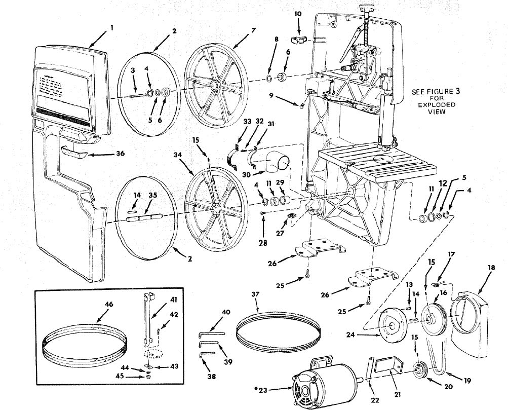
FIGURE 1
CRAFTSMAN 12-INCH BAND SAW/SANDER, MODEL 113.243300 & 113.243311
Always order by Part Number — not by Key Number
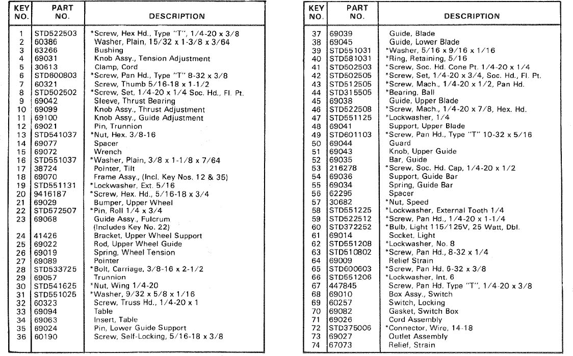
FIGURE 1 PARTS LIST
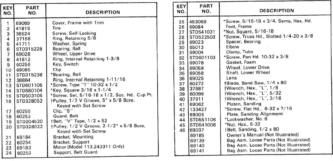
*Standard Hardware Item — May Be Purchased Locally.
†Stock Item — May be secured through the Hardware Department of most Sears or Simpsons-Sears Retail Stores or Catalog Order Houses.
repair parts
CRAFTSMAN 12-INCH BAND SAW/SANDER, MODEL 113.243300 & 113.243311
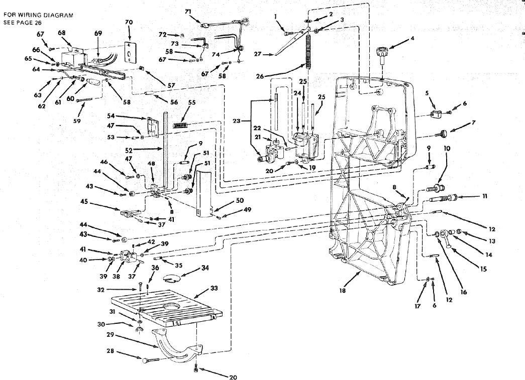
FIGURE 2
CRAFTSMAN 12-INCH BAND SAW/SANDER, MODEL 113.243300 & 113.243311
FIGURE 2 PARTS LIST
*Standard Hardware Item — May Be Purchased Locally.
†Stock Item — May be secured through the Hardware Department of most Sears or Simpsons-Sears Retail Stores or Catalog Order Houses.
CRAFTSMAN 12-INCH BAND SAW/SANDER, MODEL 113.243300 & 113.243311
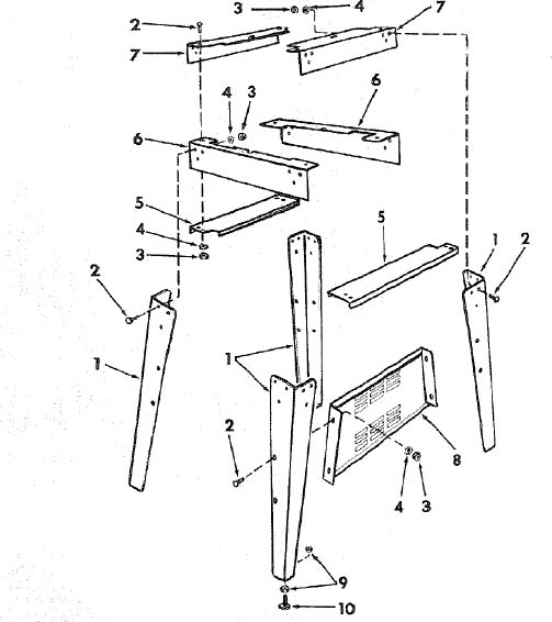
FIGURE 3
SUPPLIED WITH MODEL 113.243311 ONLY
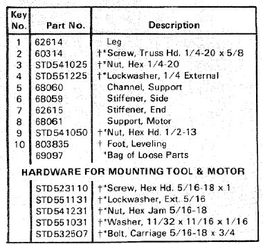
*Standard Hardware Item — May Be Purchased Locally
†All Parts Contained In Loose Parts Bag
CRAFTSMAN 12-INCH BAND SAW/SANDER, MODEL 113.243300 & 113.243311
NOTE:
ANY ATTEMPT TO REPAIR THIS MOTOR MAY CREATE A HAZARD UNLESS REPAIR IS DONE BY QUALIFIED SERVICE TECHNICIAN.
REPAIR SERVICE IS AVAILABLE AT YOUR NEAREST SEARS STORE.
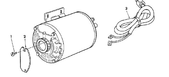
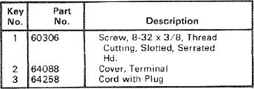
FIGURE 4 — MOTOR PART NO. 69183
SUPPLIED WITH MODEL 113.243311 ONLY
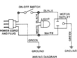
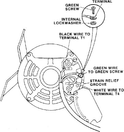
MOTOR CONNECTIONS
WARNING: FOR YOUR OWN SAFETY, NEVER CONNECT PLUG TO POWER SOURCE OUTLET UNTIL ALL ASSEMBLY STEPS ARE COMPLETED.
- Open motor connector box cover located on left end of motor ( viewed from rear of saw) using a flat blade screwdriver.
- Remove GREEN SCREW and lockwasher and insert screw through round metal terminal on the end of the GREEN wire of power cord with lockwasher between terminal and motor frame. (See illus.)
- Reinsert GREEN SCREW in the threaded hole. Tighten securely.
- Insert terminal end of WHITE wire on spade terminal marked T4 on the motor. Push terminal firmly until seated.
- Insert terminal end of BLACK wire on spade terminal marked T1 on the motor. Push terminal firmly until seated.
- Close motor connector box being sure that power cord is seated in the largest strain relief groove, and tighten box cover screws.
NOTES
NOTES
| SEARS | |
|---|---|
| owners manual | 12-INCH BAND SAW/SANDER |
| SERVICE | Now that you have purchased your 12-Inch Band Saw/Sander should a need ever exist for repair parts or service, simply contact any Sears Service Center and most Sears, Roebuck and Co. stores. Be sure to provide all pertinent facts when you call or visit. |
| MODEL NO. | |
| 113.243300 | |
| SAW ONLY | |
| MODEL NO. | |
| 113.243311 | The model number of your 12-Inch Band Saw/Sander will be found on a plate at the righthand side of the saw. |
| SAW WITH LEGS AND MOTOR | |
| WHEN ORDERING REPAIR PARTS, ALWAYS GIVE THE FOLLOWING INFORMATION: | |
| HOW TO ORDER | |
| REPAIR PARTS | PART NUMBER PART DESCRIPTION |
| MODEL NUMBER NAME OF ITEM | |
| 113.243300 12-Inch Band Saw/Sander | |
| 113.243311 | |
| All parts listed may be ordered from any Sears Service Center and most Sears stores. If the parts you need are not stocked locally, your order will be electronically transmitted to a Sears Repair Parts Distribution Center for handling. |
Sold by SEARS, ROEBUCK AND CO., Chicago, IL. 60684 U.S.A.
Parts & More
Chest Freezer
Front-Engine Lawn Tractor
Gas Pressure Washer
Gas Snowblower
Ice Cream Maker
Microwave/Hood Combo
Parts
Riding Mowers & Tractors
Side-By-Side Refrigerator
Top-Mount Refrigerator