- Kenmore refrigerator water filters
- Whirlpool refrigerator water filters
- Samsung refrigerator water filters
- GE refrigerator water filters
- LG refrigerator water filters
- Frigidaire refrigerator water filters
- KitchenAid refrigerator water filters
- Maytag refrigerator water filters
- Kenmore Elite refrigerator water filters
- Estate refrigerator water filters
- GE Profile refrigerator water filters
- Amana refrigerator water filters
- Bosch refrigerator water filters
- Dacor refrigerator water filters
- Electrolux refrigerator water filters
Top DIY repair help
View All Repair Categories
Appliances
Lawn & Garden
Power Tools
Home Improvement
Sports & Leisure
Heating & Cooling
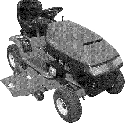
Snapper LT200H48IBV2 front-engine lawn tractor manual
Are you looking for information on using the Snapper LT200H48IBV2 front-engine lawn tractor? This user manual contains important warranty, safety, and product feature information. View the user manual below for more details. Want a copy for yourself? Download or print a free copy of the user manual below.
TRACTOR (OWNERS) SERIES I(viewing)Download PDF
Safety Instructions & Operator’s Manual for
SNAPPER®
LAWN TRACTOR
HYDROSTATIC DRIVE
ELECTRIC CLUTCH
SERIES I
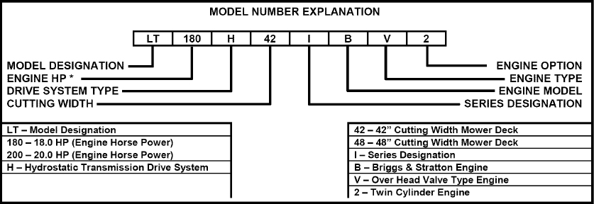
| MODELS |
|---|
| LT180H42IBV |
| LT200H42IBV2 |
| LT200H48IBV2 |
Thank you for buying a SNAPPER product! Before operating the Lawn Tractor, read and follow the “IMPORTANT SAFETY INSTRUCTIONS” on pages 2 thru 4, all other instructions contained in this manual and the accompanying booklet “About Power Mower Safety”. Lawn mowers and all power equipment can be potentially dangerous if used improperly. REMEMBER: SAFETY REQUIRES CAREFUL USE IN ACCORDANCE WITH INSTRUCTIONS AND COMMON SENSE!
NOTE: Specifications are correct at time of printing and are subject to change without notice.
* Actual sustained equipment horsepower will likely be lower due to operating limitations and environmental factors.
COPYRIGHT © 2004
SNAPPER PRODUCTS INC.
ALL RIGHTS RESERVED
SNAPPER® McDonough, GA., 30253 U.S.A.
MANUAL NO. 7-2865 (I.R. 6/15/04)
 IMPORTANT SAFETY INSTRUCTIONS
 WARNING: This powerful cutting machine is capable of amputating hands and feet and can throw objects that can cause injury and damage! Failure to comply with the following SAFETY instructions could result in serious injury or death to the operator or other persons. The owner of the machine must understand these instructions and must allow only persons who understand these instructions to operate machine. Each person operating the machine must be of sound mind and body and must not be under the influence of any substance, which might impair vision, dexterity or judgment. If you have any questions pertaining to your machine which your dealer cannot answer to your satisfaction, call or write the Customer Service Department at SNAPPER, McDonough, Georgia 30253. Phone: (1-800-935-2967).
PROTECTION FOR CHILDREN
Tragic accidents can occur if the operator is not alert to the presence of children. Children are often attracted to the machine and the mowing activity. Children who have been given rides in the past may suddenly appear in the mowing area for another ride and be run over or backed over by the machine. Never assume that children will remain where you last saw them.
- KEEP children out of the mowing area and under the watchful care of a responsible adult other than the operator.
- DO NOT allow children in yard when machine is operated (even with the blade OFF).
- DO NOT allow children or others to ride on machine, attachments or towed equipment (even with the blades OFF). They may fall and be seriously injured.
- DO NOT allow pre-teenage children to operate machine.
- ALLOW only responsible adults & teenagers with mature judgment under close adult supervision to operate machine.
- DO NOT operate blades in reverse. STOP BLADES. LOOK and SEE behind and down for children, pets and hazards before and while backing.
- USE EXTRA CARE when approaching blind corners, shrubs, trees, or other objects that may obscure vision.
PROTECTION AGAINST TIPOVERS
Slopes are a major factor related to loss-of-control and tip-over accidents, which can result in severe injury or death. All slopes require extra CAUTION. If you cannot back up the slope or if you feel uneasy on the slope, DO NOT mow it. Use extra care with grass catchers or other attachments; these affect the handling and the stability of the machine.
- DO NOT operate machine on slopes exceeding 15 degrees (27% grade).
- Exercise EXTREME CAUTION on slopes above 10 degrees (18% grade). Turn blades OFF when traveling uphill. Use a slow speed and avoid sudden or sharp turns.
- DO NOT operate machine back and forth across face of slopes. Operate up and down. Practice on slopes with blades off.
- AVOID starting, stopping or turning on slopes. If machine stops going uphill or tires lose traction, turn blades OFF and back slowly straight down the slope.
- STAY ALERT for holes and other hidden hazards. Tall grass can hide obstacles. Keep away from ditches, washouts, culverts, fences and protruding objects.
- KEEP A SAFE DISTANCE (at least 3 feet) away from edge of ditches and other drop offs. The machine could turn over if an edge caves in.
- Always begin forward motion slowly and with caution.
- Use weights or a weighted load carrier in accordance with instructions supplied with a grass catcher. DO NOT operate machine on slopes exceeding 10 degrees (18% grade) when equipped with grass catcher.
- DO NOT put your foot on the ground to try to stabilize the machine.
- DO NOT operate machine on wet grass. Reduced traction could cause sliding.
- Chose a low enough speed setting so that you will not have to stop or shift on a slope. Tires may lose traction on slopes even though the brakes are functioning properly.
- DO NOT operate machine under any condition where traction, steering or stability is doubtful.
- Always keep the machine in gear when going down slopes. DO NOT shift to neutral (or actuate hydro roll release) and coast downhill.
PREPARATION
- Read, understand, and follow instructions and warnings in this manual and on the machine, engine and attachments. Know the controls and the proper use of the machine before starting.
- Only mature, responsible persons shall operate the machine and only after proper instruction.
- Data indicates that operators age 60 and above, are involved in a large percentage of mower-related injuries. These operators should evaluate their ability to operate the mower safely enough to protect themselves and others from serious injury.
- Handle fuel with extra care. Fuels are flammable and vapors are explosive. Use only an approved fuel container. DO NOT remove fuel cap or add fuel with engine running. Add fuel outdoors only with engine stopped and cool. Clean spilled fuel from machine. DO NOT smoke.
- Practice operation of machine with BLADES OFF to learn controls and develop skills.
- Check the area to be mowed and remove all objects such as toys, wire, rocks, limbs and other objects that could cause injury if thrown by blade or interfere with mowing.
- Keep people and pets out of mowing area. Immediately STOP blades, STOP engine, and STOP machine if anyone enters the area.
- Check shields, deflectors, switches, blade controls and other safety devices frequently for proper operation and location.
- Make sure all safety decals are clearly legible. Replace if damaged.
- Protect yourself when mowing and wear safety glasses, long pants and substantial footwear.
- Know how to STOP blades and engine quickly in preparation for emergencies.
- Use extra care when loading or unloading the machine into a trailer or truck.
- Check grass catcher components frequently for signs of wear or deterioration and replace as needed to prevent injury from thrown objects going through weak or worn spots.
SAFE HANDLING OF GASOLINE
To avoid personal injury or property damage, use extreme care in handling gasoline. Gasoline is extremely flammable and the vapors are explosive
- Extinguish all cigarettes, cigars, pipes and other sources of ignition.
- Use only an approved fuel container.
- DO NOT remove fuel cap or add fuel with the engine running. Allow the engine to cool before refueling.
- DO NOT refuel the machine indoors.
- DO NOT store the machine or fuel container inside where there is an open flame, spark or pilot light such as on a water heater or other appliances.
- DO NOT fill fuel containers inside a vehicle or on a truck or trailer bed with a plastic liner. Always place the containers on the ground away from the vehicle before filling.
- Remove gas-powered equipment from the vehicle or trailer and refuel it on the ground. If this is not possible, then refuel equipment using a portable container, rather than a gasoline dispenser nozzle.
- DO NOT start gas powered equipment in enclosed vehicles or trailers.
- Keep the nozzle in contact with the rim of the fuel tank or container opening at all times until fueling is complete. DO NOT use a nozzle lock-open device
- If fuel is spilled on clothing, change clothing immediately.
- Never overfill a fuel tank. Replace fuel cap and tighten securely.
OPERATION
- Mount and dismount machine from left side. Keep clear of discharge opening at all times.
- Start engine from operator's seat, if possible. Make sure blades are OFF and parking brake is set.
- DO NOT leave machine with engine running. STOP engine, STOP blades, SET brake, and Remove key before leaving operators position of any reason.
- DO NOT operate machine unless properly seated with feet on feet rests or pedal(s).
- STOP BLADES and ENGINE and make sure blades have stopped before removing grass catcher or unclogging mower to prevent loss of fingers or hand.
- Blades must be OFF except when cutting grass. Set blades in highest position when mowing over rough ground.
- Keep hands and feet away from rotating blades underneath deck. DO NOT place foot on ground while BLADES are ON or machine is in motion.
- DO NOT operate machine without entire grass catcher or guards in place and working. DO NOT point discharge at people, passing cars, windows or doors.
- Slow down before turning.
- Watch out for traffic when near or crossing roadways.
- STOP engine immediately after striking an obstruction. Inspect machine and repair damage before resuming operation.
- Operate machine only in daylight or with good artificial light.
- Move joystick (if equipped) SLOWLY to maintain control during speed and directional changes.
- Exercise CAUTION when pulling loads. Limit loads to those you can safely control and attach loads to hitch plate as specified with SNAPPER attachment instructions.
- On slopes, the weight of the towed equipment may cause loss of traction and loss of control. When towing, travel slowly and allow extra distance to stop.
- DO NOT operate engine in enclosed areas. Engine exhaust gases contain carbon monoxide, a deadly poison.
- DO NOT discharge material against a wall or obstruction. Material may ricochet back towards the operator.
- Only use accessories approved by the manufacturer. See manufacturer’s instructions for proper operation and installation of accessories.
TOWING
- Tow only with a machine that has a hitch designed for towing. DO NOT attach towed equipment except at the hitch point.
- Follow the manufacturer’s recommendation for weight limits for towed equipment and towing on slopes.
- DO NOT allow children or others on towed equipment.
- On slopes, the weight of the towed equipment may cause loss of traction and loss of control.
Travel slowly and allow extra distance to stop.
MAINTENANCE
- DO NOT store machine or fuel container inside where fumes may reach an open flame, spark or pilot light such as in a water heater, furnace, clothes dryer or other gas appliance. Allow engine to cool before storing machine in an enclosure. Store fuel container out of the reach of children in a well ventilated, unoccupied building.
- Keep engine free of grass, leaves or excess grease to reduce fire hazard and engine overheating.
- When draining fuel tank, drain fuel into an approved container outdoors and away from open flame.
- Check brakes frequently; adjust, repair or replace as needed.
- Keep all bolts, nuts and screws properly tight. Check that all cotter pins are in proper position.
- Always provide adequate ventilation when running engine. Exhaust gases contain carbon monoxide, an odorless and deadly poison.
- Disconnect negative (black) cable from battery before performing maintenance or service. Cranking engine could cause injury.
- DO NOT work under machine without safety blocks.
- Service engine and make adjustments only when engine is stopped. Remove spark plug wire(s) from spark plug(s) and secure wire(s) away from spark plug(s).
- DO NOT change engine governor speed settings or overspeed engine.
- Lubricate machine at intervals specified in manual to prevent controls from binding.
- Mower blades are sharp and can cut. Wrap the blades or wear heavy leather gloves and use CAUTION when handling them.
- DO NOT test for spark by grounding spark plug next to spark plug hole; spark plug could ignite gas exiting engine.
- Have machine serviced by an authorized SNAPPER dealer at least once a year and have the dealer install any new safety devices.
- Maintain or replace safety and instruction labels as necessary.
- Use only genuine SNAPPER replacement parts to assure that original standards are maintained.
TABLE OF CONTENTS
- IMPORTANT SAFETY INSTRUCTIONS
- TABLE OF CONTENTS
- SECTION 1 - FAMILIARIZATION
- SECTION 2 - OPERATING INSTRUCTIONS
- SECTION 3 - MAINTENANCE INSTRUCTIONS
- SECTION 4 - ADJUSTMENTS & REPAIR
- Engine Adjustments & Repair
- Mower Deck & Component Adjustments
- Blade Brake Adjustment
- Blade Belt Adjustment
- 42" Side To Side Deck Level Adjustment
- 42" Front To Rear Deck Level Adjustment
- 48" Side To Side Deck Level Adjustment
- 48" Front To Rear Deck Level Adjustment
- Brake Adjustment
- Steering Adjustment
- Shifter Adjustment
- Traction Drive Belt Adjustment
- Mower Blade Service
- Traction Drive Belt Removal/Replace
- Deck Belt Removal & Replacement
- Battery Service
- AVAILABLE ACCESSORIES
- SECTION 5 - ELECTRICAL SYSTEM
- TROUBLESHOOTING GUIDE
- MAINTENANCE SCHEDULE
- MAINTENANCE PARTS
- WARRANTY
- PRIMARY MAINTENANCE
- PRODUCT REGISTRATION FORM
IMPORTANT
The figures and illustrations in this manual are provided for reference only and may differ from your specific model. Contact your Snapper dealer if you have questions
Section 1 - FAMILIARIZATION
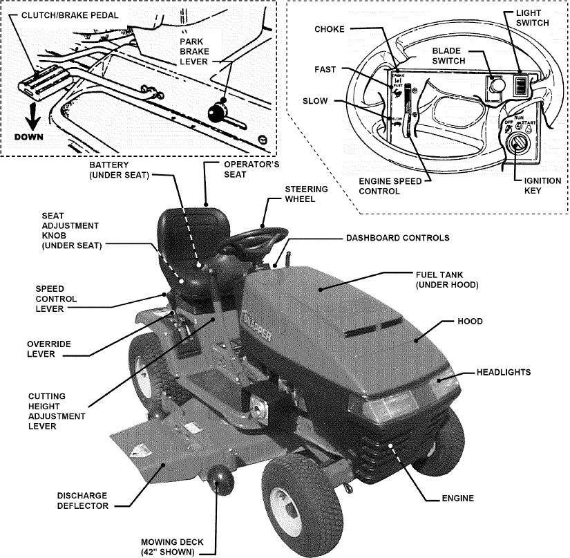
FIGURE 1.1
COMPONENTS
The nomenclature drawings above, illustrate the essential components of the SNAPPER Lawn Tractor. It is recommended that all operators of this equipment become thoroughly familiar with the components and their operation BEFORE OPERATING. Specific details involving the engine are found in the separate Engine Owner’s Manual.
Study the Important Safety Instructions, this Operator’s Manual and Engine Owner’s Manual before operating this machine. Keep these manuals available for future reference.
CONTROLS
All operators should be acquainted with the operator’s controls before attempting start-up or operation of the Lawn Tractor. See the Control Panel drawing above.
Section 2 - OPERATING INSTRUCTIONS
2.1 PRE-START CHECKLIST
Make the following checks and perform service as required before each start-up.
2.1.1. Check tires and add air as needed to bring pressure to 12 P.S.I. in front tires and 12 P.S.I. in rear tires.
2.1.2. Check guards, deflectors and covers to make sure all are in place and securely tightened. If guards are missing or damaged, replace BEFORE using mower.
2.1.3. Check engine oil and add oil as needed to bring level up to, but not over, the FULL mark. Refer to engine owner’s manual for oil specifications. See Figure 2.1.
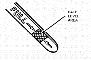
FIGURE 2.1
2.1.4. Check blade switch to ensure it moves freely. Manually pull switch out to the “ON” position and push switch down to the “OFF” position.
2.1.5. Clean exterior surfaces of cutting deck, engine and tractor of any accumulation of dirt, grass, oil, etc. Keep engine air intake screens and cooling fins clean at all times.
2.1.6. With engine “OFF” move the tractor outside and add fuel to the fuel tank. Securely tighten fuel cap after refueling. Refer to engine owner’s manual for fuel specifications. See Figure 2.2.
2.1.7. Check Reverse Lockout Mechanism. Refer to Section “Reverse Lockout Mechanism”.
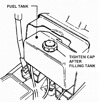
FIGURE 2.2
2.2 OPERATOR’S SEAT ADJUSTMENT
2.2.1. FRONT TO REAR ADJUSTMENT
1. With the engine “OFF”, raise operator's seat and loosen the two adjusting knobs on the seat support. Lower the seat. Sit in the operator's seat and slide the seat forward or backward until the clutch/brake pedal can be fully depressed comfortably. Raise seat and tighten the adjusting knobs to secure seat in position. See Figure 2.3.
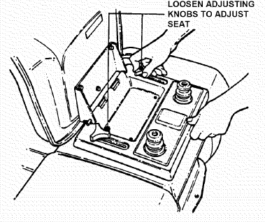
FIGURE 2.3
2.3 STARTING & OPERATION
2.3.1. STARTING ENGINE
1. Take a comfortable position in seat of machine, look around to make sure that the area you are going to mow is clear of people, children and pets. Take note of any stationary obstacles!
NOTE: The interlock system will prevent the engine from starting if the blade switch is in the “ON” (up) position or if the clutch/brake pedal is not fully depressed. If the interlock system ever fails to work, DO NOT OPERATE the tractor until the interlock has been repaired.
2. Push blade switch down to the “OFF” position. See Figure 2.4.
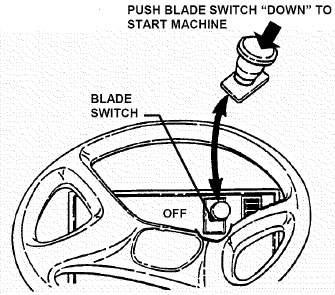
FIGURE 2.4
3. Depress the clutch/brake pedal fully. See Figure 2.5.
4. Move speed control lever to neutral.
NOTE: The seat interlock will shut off the engine if the operator gets off the seat without setting the parking brake or if the blades are running. If the interlock ever fails to work, DO NOT OPERATE the tractor until the interlock has been repaired.
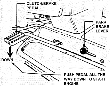
FIGURE 2.5
5. Choke engine for cold starting by moving engine speed control to “CHOKE” position. NOTE: Some models are equipped with a separate choke control, located on the dash of the tractor. Pull the control “OUT” to choke position to start a cold engine. Little or no choking will be needed when restarting a warm engine. Insert key in switch. Turn key to “START” position to crank engine and hold until engine starts, then release key to “RUN” position. See Figure 2.6.
NOTE: DO NOT crank engine for more than five seconds at a time. This will help prevent the starter from overheating and/or running down the battery. If cranking time is more than five seconds, locate and correct cause of starting problem.
6. After engine starts, release key, move the engine speed control to “FAST” position and allow engine to warm up before proceeding. See Figure 2.6.
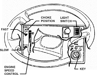
FIGURE 2.6
WARNINGDO NOT leave machine with engine running. Stop engine. Stop blades. Set parking brake. Remove key.
2.3.2. STARTING WHEEL DRIVE
1. Shift speed control lever to neutral.
2. Start engine. Refer to Section “STARTING ENGINE”.
3. Release clutch/brake pedal.
4. Slowly shift speed control lever forward for forward motion or to the rear for reverse motion. See Figure 2.7.
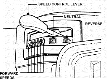
FIGURE 2.7
2.3.3 STARTING MOWER BLADE
1. Start engine. Refer to Section “STARTING ENGINE”.
2. Pull blade switch OUT to engage blade. See Figure 2.8.
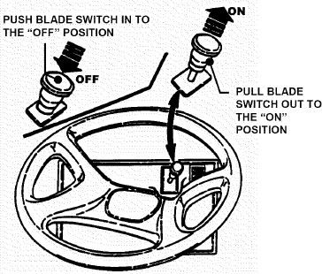
FIGURE 2.8
WARNINGDO NOT operate blades with machine in reverse. STOP BLADES. LOOK and SEE behind and down for children, pets and hazards before and while backing.
2.4 STOPPING ENGINE, BLADE, WHEEL DRIVE
2.4.1. STOPPING ENGINE
1. Stop engine by turning key to the “OFF” position. See Figure 2.9.
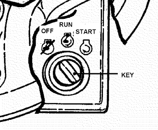
FIGURE 2.9
2.4.2. STOPPING WHEEL DRIVE
1. Fully depress clutch/brake pedal to stop wheel drive. See Figure 2.10.
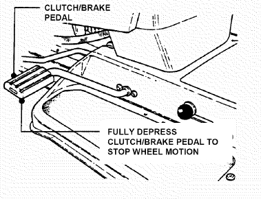
FIGURE 2.10
2.4.3. STOPPING MOWER BLADES
1. Stop mower blade by pushing blades switch IN to disengage blades. See Figure 2.11.
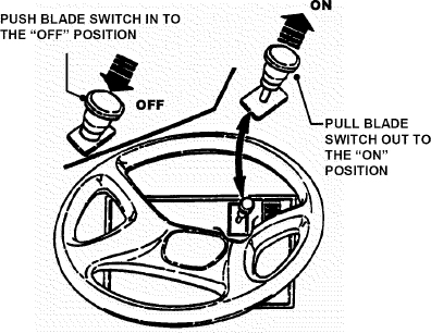
FIGURE 2.11
WARNINGOnce blades are disengaged, they should come to a complete stop in 5 seconds or less. If the blades continue to rotate after 5 seconds, the blade brake must be repaired. Return machine to an authorized SNAPPER dealer. DO NOT continue to operate machine until blade brake has been repaired and functioning properly.
2.4.4. SETTING PARK BRAKE
1. Fully depress clutch/brake pedal.
2. Move park brake lever up into slot. See Figure 2.12.
3. Release pedal.
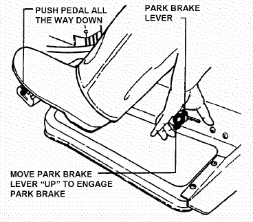
FIGURE 2.12
2.4.5. RELEASING PARK BRAKE
1. Fully depress clutch/brake pedal. Move park brake lever “DOWN” to release park brake. Release clutch/brake pedal. See Figure 2.13.
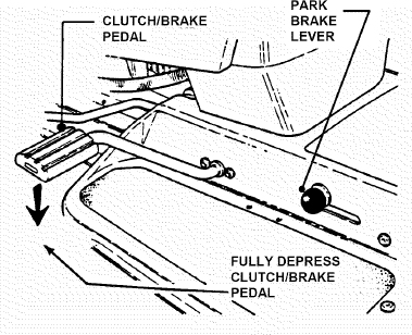
FIGURE 2.13
2.5. CUTTING HEIGHT ADJUSTMENT
1. Depress lock button on cutting height adjustment lever. See Figure 2.14.
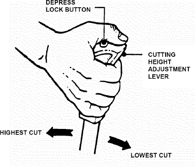
FIGURE 2.14
2. Raise or lower deck to any of six positions as desired Release lock button.
WARNINGDO NOT park machine on slopes.
2.6. ROLLING TRACTOR WITH ENGINE OFF
2.6.1. Rolling Hydro Models
1. With engine “OFF”, move to rear of tractor.
2. Pull the roll release control all the way out to disengage the hydro transmission. See Figure 2.15.
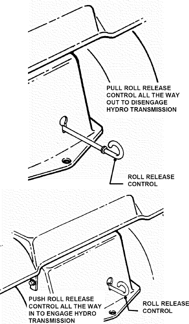
FIGURE 2.15
3. Move tractor to desired location.
4. Set park brake.
5. Push roll release control all the way in to engage hydro transmission. See Figure 2.15.
NOTE: The transmission will not propel the tractor if it is left in the “ROLL” position.
WARNINGDO NOT disengage the hydro transmission and coast down slopes. DO NOT use Roll Release Control to disengage hydro transmission unless machine motion can be controlled and engine is off.
2.7. REVERSE LOCKOUT MECHANISM
Data indicates that tragic back-over accidents occur each year. These accidents usually involve unsupervised children. Many times these children have been given rides on the machine and have been trained to view this potentially dangerous piece of machinery as fun rather than being taught how to avoid danger.
This riding mower has a Reverse Lockout Mechanism. This mechanism prevents the mower from being shifted into reverse with the blades running. To shift into reverse you must first stop the blades and then shift to reverse. It is our recommendation that this mechanism remain functional and the operator of this equipment develop the habit of never backing up with the blades running. As the Safety Instructions Indicate, DO NOT operate blades with machine in reverse. STOP BLADES, LOOK AND SEE BEHIND AND DOWN for children, pets and hazards before and while backing.
We realize that this could cause a change to your previous mowing method but we encourage you to adjust to this new system. Do not defeat the Reverse Lockout Mechanism.
If you operate your mower near roadways or use attachments that require quicker shifting to reverse, there is an override lever provided. This lever can be pushed and held before engaging the blades and will allow reverse operation until the blade switch is pushed in to the “OFF” position, at which time the system will return to its Reverse Lockout mode. This feature should never be selected unless you are absolutely sure that no children or others are present in the mowing area and that all children are away and supervised by a responsible adult.
2.7.1. Reverse Lockout Mechanism Override
1. Stop machine. Stop blades.
2. Depress and hold Override Lever.
3. Pull blade switch “OUT” to engage blade.
4. Release Override Lever
WARNINGLOOK and SEE behind and down for children, pets and hazards before and while backing.
IMPORTANT! DO NOT use the Reverse Lockout Mechanism Override as the normal operating mode. To return to the Reverse Lockout Mechanism mode, disengage (STOP) blades by pushing blade switch in to the “OFF” position. The Override will reset to Reverse Lockout.
2.7.2. Check the Reverse Lockout Mechanism
Before each use, check the Reverse Lockout Mechanism for proper function. The following procedure requires the operation of the engine and blades. Before proceeding, Read, Understand, and Follow all Safety Instructions and Warnings in this manual and on the machine.
1. Complete Pre-Start Checklist.
2. Move machine to clear open area. DO NOT allow children or others in area.
3. Start engine.
4. Pull blade switch “OUT” to engage blades.
5. Reverse Lockout Mechanism must prevent speed control lever from going into reverse.
WARNINGDO NOT operate machine if Reverse Lockout Mechanism is not functioning properly. Contact your SNAPPER dealer immediately for assistance.
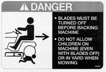
DANGERLOOK and SEE behind and down for children, pets and hazards before and while backing.
BLADES must be turned off before backing machine.
DO NOT allow children on machine (even with blades off) or in yard when mowing.
Section 3 - MAINTENANCE
3.1 INTRODUCTION
To retain the quality of the Tractor, use genuine SNAPPER replacement parts only. Contact a local SNAPPER dealer for parts and service assistance. For the correct part or information for a particular Tractor, always mention the model and serial number. SNAPPER recommends returning the Tractor to an authorized SNAPPER dealer annually for inspection and addition of any new devices, which might upgrade the safety of the Tractor. For the nearest SNAPPER dealer in your area, check the yellow pages under the heading LAWN MOWERS. For engine parts and service, look for the engine manufacturer's dealers under the heading, ENGINES - gasoline.
3.2 SERVICE - AFTER FIRST 5 HOURS
WARNINGDO NOT attempt any adjustments, maintenance or service with the engine or blades running. STOP blades. STOP engine. Set brake. Remove key. Remove spark plug wire from spark plug and secure wire away from spark plug. Engine and components can be extremely hot Avoid bums by allowing engine and components sufficient time to cool.
3.2.1. CHANGE ENGINE OIL
The engine is equipped with a Fastex™ oil drain.
1. Rotate drain body counterclockwise and pull out to open drain. See Figure 3.1.
2. Drain oil into a 2 quart container placed beneath end of oil drain.
3. After all oil has drained, push drain body "IN" and rotate clockwise to close.
4. Fill engine with new motor oil as specified in engine owner's manual.
WARNINGThe following procedure requires the engine and blades to be operated. Exercise extreme caution. Clear area of loose parts & tools first. Only operate blades when seated in the operator’s seat.
3.2.2. CHECK BLADE BRAKE
1. Check blade brake for proper function. Blades should stop rotating in 5 seconds or less after pushing the blade switch “IN” to the OFF disengaged position.
2. If blades continue to rotate longer than 5 seconds do not operate machine. Contact your SNAPPER dealer for assistance.
3.2.3. CHECK MOWER BLADES
1. Remove deck from tractor.
2. Carefully position deck to access blade.
3. Check blade for sharpness, wear and damage. Refer to Section “BLADE WEAR LIMITS”.
4. Check blade for straightness. Refer to Section “ADJUSTING MOWER BLADE”.
5. Check torque of blade mounting bolts. Torque to: 42" deck - 30 to 40 ft lbs. See Figure 3.2. 48" deck - 70 to 80 ft lbs.
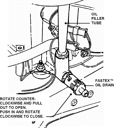
FIGURE 3.1
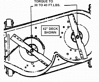
FIGURE 3.2
WARNINGBlades must stop rotating in 5 seconds or less after blades have been turned off. DO NOT operate machine until blade brake has been repaired and functioning properly. Contact your SNAPPER dealer for assistance.
WARNINGDO NOT attempt any adjustments, maintenance, service or repairs with the engine running. Stop engine. Stop blade. Engage parking brake. Remove key. Remove spark plug wire from spark plug and secure away from plug. Engine and components are HOT. Avoid serious burns, allow all parts to cool before working on machine.
3.2.4. CHECK DECK DRIVE BELT
1. The idler and spring provide proper belt tension and require no adjustment. If belt is frayed, slit, severed or belt strands exposed, replace belt before operating mower.
SERVICE - EVERY 25 OPERATING HOURS
3.3.1. CHECK ENGINE
1. Engine Cooling System
The engine cooling system consists of an engine shroud and engine fins. These should be kept clean and free of debris as needed or cleaned.
2. Engine Oil
Change engine oil. See Section on CHANGE ENGINE OIL. Refer to engine owner’s manual for oil specifications.
3. Oil Filter
Change engine oil filter. Refer to engine owner's manual for filter specifications.
4. Fuel Filter
Refer to engine owner’s manual for service instructions.
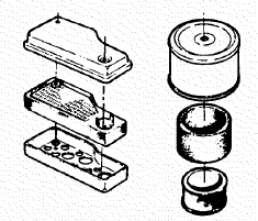
5. Air Filter - Twin Cylinder Engine
Refer to engine owner’s manual for service instructions.
a. Change air filter. Remove bolts that secure air cleaner cover to the engine. See Figure 3.3.
IMPORTANT: When cover is removed, you are viewing the carburetor side of the air filter, which will appear clean. Remove filter and pre-cleaner for inspection.
b. Refer to engine owner's manual for cleaning and service instructions. Remove and clean engine air pre-cleaner. Remove and replace engine air cleaner. See Figure 3.4. Install pre-cleaner and air cleaner per engine owner’s manual.
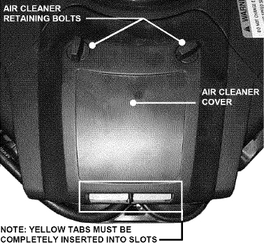
FIGURE 3.3
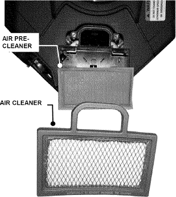
FIGURE 3.4
c. Reinstall air cleaner cover. Insert tabs located on the engine cover into corresponding slots in air cleaner cover. IMPORTANT: The yellow tabs must be completely inserted into air cleaner cover or the compartment will not be completely sealed to prevent debris from entering into the carburetor.
d. Reinstall bolts that secure air cleaner cover to the engine. Tighten securely.
6. Air Filter - Single Cylinder Engine
Refer to engine owner’s manual for service instructions.
a. Change air filter Pull up and rotate the air cleaner latch to remove cleaner cover. See Figure 3.5.
IMPORTANT: When cover is removed, you are viewing the carburetor side of the air filter, which will appear clean. Remove filter and pre-cleaner for inspection.
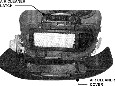
FIGURE 3.5
b. Refer to engine owner's manual for cleaning and service instructions. Remove and clean engine air pre-cleaner. Remove and replace engine air cleaner. See Figure 3.6. Install pre-cleaner and air cleaner per engine owner's manual.
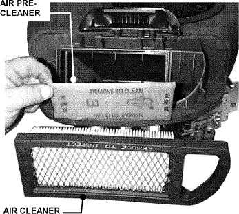
FIGURE 3.6
c. Reinstall air cleaner cover. Insert tabs located at the bottom of the cover into corresponding slots in engine cover. Position cover and engage latch over cover and rotate and push down to lock.
3.3.2. SAFETY INTERLOCK SYSTEM CHECKS
This machine is equipped with an electrical safety interlock system that is provided for the safety of the operator and others. All safety devices must be in place and functioning properly before operating the machine. Perform the following interlock system checks periodically during the operating season. Contact your authorized Snapper dealer if you have questions.
WARNINGDO NOT operate machine if any safety interlock or safety device is not in place and functioning properly. DO NOT attempt to defeat, modify or remove any safety device.
ENGINE MUST NOT START IF:
1) Clutch/Brake Pedal not fully depressed OR,
2) Blade Switch in the “ON” blades engaged position.
ENGINE SHOULD START IF:
1) Blade Switch in the “OFF” blades disengaged position AND,
2) Clutch/Brake Pedal fully depressed.
ENGINE MUST BEGIN TO STOP IF:
1) Operator rises off of seat with Blade Switch in “ON” blades engaged position OR,
2) Operator rises off of seat with Clutch/Brake Pedal not fully depressed.
IMPORTANT: Engine will continue to run if Operator becomes seated prior to engine coming to a complete stop. To restart the blades, first move the Blade Switch to the “OFF” position and then back to the “ON” position. After coming to a complete stop, the blade switch must be moved to the “OFF” position and the Clutch/Brake Pedal fully depressed before engine can be restarted. Engine and blades must come to a complete stop within 5 seconds after the operator rises off the seat or the blade switch is moved to the “OFF” position.
3.3.3. MOWER COMPONENTS
1. Check deck drive belt for proper tension. Refer to Section, “CHECK DECK DRIVE BELT”.
2. Check blades for sharpness, wear, damage and torque. Refer to Section on “MOWER BLADE SERVICE”.
3. Check mower deck for proper levelness. Refer to Section “MOWER DECK ADJUSTMENT - LEVELNESS”.
4. Clean mower deck.
a. Remove key from ignition switch.
b. Remove deck.
c. Clean underside of mower deck, removing all accumulation of grass clippings and debris.
d. Clean top of deck, removing all grass clippings and debris.
5. Lubricate spindles with 1 to 3 shots of general purpose grease from grease gun.
6. Lubricate all mower deck linkage pivot points with a light coat of motor oil.
7. Lubricate idler arms with 1 to 3 shots of general purpose grease from grease gun.
3.3.4. CHECK BLADE BRAKE
1. Refer to Section “CHECK BLADE BRAKE”.
3.3.5. TRACTOR LUBRICATION
1. Front Wheel Bearings
Lubricate each front wheel bearing through the grease fitting on wheel hub. Using general purpose grease in a grease gun, add grease until grease purges from bearing. See Figure 3.7.
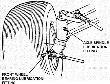
FIGURE 3.7
2. Axle Spindles
Lubricate each axle spindle with 1 to 3 shots of general purpose grease. See Figure 3.7.
3. Clutch/Brake Pivot
The clutch/brake pivot is located on the L.H. underside of the tractor and is lubricated with one shot of general purpose grease. See Figure 3.8.
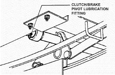
FIGURE 3.8
4. Steering Sector Gear
Lubricate with a light coat of general purpose grease. See Figure 3.9.
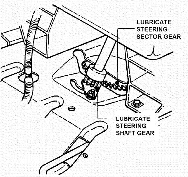
FIGURE 3.9
5. Steering Shaft
Lubricate steering shaft wear points with a light coat of 30 wt. Motor oil.
6. Steering Drag Link
Lubricate both ends of steering drag link with a small amount of 30 wt. motor oil from an oil can. See Figure 3.10.
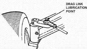
FIGURE 3.10
7. Steering Tie Rod
Lubricate both ends of steering tie rod with a small amount of 30 wt. motor oil from an oil can. See Figure 3.11.
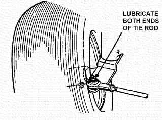
FIGURE 3.11
8. Park Brake Lever
Using 30 wt. motor oil, lubricate the park brake lever mechanism pivot points, which are located on the left hand underside of tractor. See Figure 3.12. Lubricate mechanism with a thin coat of 30 wt. motor oil.
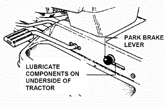
FIGURE 3.12
9. Deck Lift Mechanism
Lubricate all wear and pivot points of the deck lift
3.4 ANNUALLY (END OF EACH SEASON)
Perform all maintenance as described in Section “SERVICE - EVERY 25 OPERATING HOURS”. Also see Service Schedule.
3.4.1. ENGINE
1. Service engine according to engine owner's manual.
3.4.2. FUEL FILTER
1. Service fuel filter as instructed below, on COLD ENGINE ONLY!
NOTE: It may be necessary to drain the fuel tank before removing fuel filter to prevent spillage of gasoline.
2. Locate fuel filter. Remove hose clamps and fuel hoses from both sides of fuel filter.
3. Install new fuel filter part number 1-4359. See Figure 3.13.

FIGURE 3.13
4. Fill fuel tank with fresh gasoline. Refer to engine owner's manual for fuel specifications.
3.4.3. SPARK PLUG
Remove and replace engine spark plug. Refer to engine owner's manual for correct replacement plug and gap specifications.
3.4.4. HYDROSTATIC TRANSMISSION OIL
The hydrostatic transmission does not require maintenance. If any problems arise return immediately to a Snapper dealer.
Section 4 - ADJUSTMENT & REPAIR
WARNING DO NOT attempt any adjustments, maintenance or service with the engine or blades running. STOP blades. STOP engine. Set brake. Remove key. Remove spark plug wire from spark plug and secure wire away from spark plug. Engine and components can be extremely hot. Avoid burns by allowing engine and components sufficient time to cool.
4.1 ENGINE ADJUSTMENTS & REPAIR
Refer to the engine owner's manual for those adjustments and/or repairs that can be made by the owner.
4.2 MOWER DECK & COMPONENT ADJUSTMENTS
The following mower deck and component adjustments and repairs can be made by the owner. However, if there is difficulty in achieving these adjustments and repairs, it is recommended that these repairs be made by an authorized SNAPPER dealer.
WARNING Blades must stop rotating in 5 seconds or less after blades have been turned off. DO NOT operate machine until blade brake has been repaired and functioning properly. Contact your SNAPPER dealer for assistance.
4.2.1. BLADE BRAKE ADJUSTMENT
This SNAPPER Lawn Tractor is equipped with an electric clutch/brake that should stop blade rotation in 5 seconds or less after being turned off. If blades continue to rotate longer than 5 seconds, adjustment or replacement is required. When properly adjusted, a .012” to .014” feeler gauge will fit thru the three inspection slots located on the side of the clutch as shown. See Figure 4.1. Excessive clearance can adversely affect the function of the clutch and produce blade stop times over 5 seconds. To adjust, turn the three adjusting nuts clockwise to reduce clearance. The clearance at each of the three slots must be set the same.
4.2.2. BLADE BELT ADJUSTMENT
The 42” and 48” mower deck drive belts do not require any adjustment. If the belt does not drive blade properly, replace belt as needed.
4.2.3. MOWER DECK ADJUSTMENT (LEVELNESS) 1. SIDE-To-SIDE (42” Decks)
Before making deck leveling adjustments, check the tire pressure. Check tires and add or release air as needed to bring pressure to 12 PSI in front and 12 PSI in rear tires. If tires are properly inflated and mowing is still uneven, adjust side-to-side deck levelness as follows:
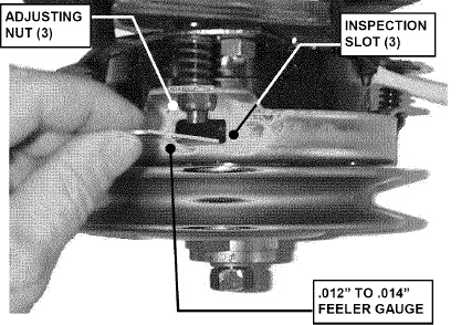
FIGURE 4.1
a. Place machine on a smooth level surface.
b. Turn engine off and remove key, remove spark plug wire(s) from spark plug(s) and secure wire(s) away from plug(s).
c. Place a piece of angle iron, pipe, or similar object under center of deck at the rear.
d. Disconnect rear sector plates and allow center, rear of deck to rest on angle iron.
e. Measure the distance from blade tips to floor. If the measurement is within 1/8” from side-to-side, the deck levelness is satisfactory. If the difference from side-to-side is greater than 1/8”, an adjustment will have to be made. See Figure 4.2.
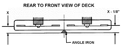
FIGURE 4.2
f. Loosen the shoulder bolt that retains the eccentric.
g. Turn eccentric “UP” or “DOWN” as required until blade tips are within 1/8” of the same distance from the floor. See Figure 4.3.
h. Tighten shoulder bolt loosened in Step “f”.
i. Readjust rear sector plates to align with holes in support brackets.
WARNING DO NOT attempt any adjustments, maintenance or service with the engine or blades running. STOP blades. STOP engine. Set brake. Remove key. Remove spark plug wire from spark plug and secure wire away from spark plug. Engine and components can be extremely hot. Avoid burns by allowing engine and components sufficient time to cool.
j. Reconnect sector plates, remove angle iron, pipe, etc. and recheck side to side level. Adjust as needed to result in blade tips being within 1/8” of the same distance from the floor.
k. Proceed to check front to rear deck pitch.
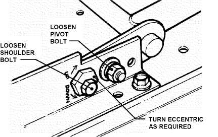
FIGURE 4.3
4.2.4. MOWER DECK ADJUSTMENT (LEVELNESS) FRONT-To-REAR (42” Decks)
1. Remove hair pins and washers securing sector plates to rear lift arms. See Figure 4.4.
2. Move sector plate as required to raise or lower the rear of deck.
NOTE: The deck should be set so that the rear of the deck is 1/4” lower than the front.
3. If the sector plates are in their lowest setting and proper level cannot be obtained, adjust the front lift rod as follows:
4. Move deck lift lever to #5 position.
5. Place a 2 × 4 wooden block on edge under front center of deck.
6. Place a 3 × 3 wooden block under rear center of deck.
7. Remove hair pins and washers securing sector plates. Lower rear of deck onto 3 × 3 block.
8. Remove hair pin and washer securing front lift cable to front lift arm. See Figure 4.5.
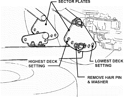
FIGURE 4.4
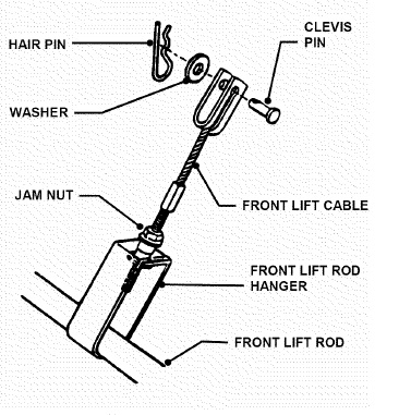
FIGURE 4.5
9. Remove front lift cable and rest front of deck onto 2 × 4 block.
10. Loosen jam nut on front lift cable. See Figure 4.5.
11. Rotate front lift cable until it can be reinstalled into front lift arm without lifting deck.
12. Secure lift cable to lift arm with washer and hair pin. Secure jam nut.
13. Reinstall sector plates onto rear hanger brackets and secure with washers and hair pins.
14. Raise deck and remove wooden blocks.
15. Repeat steps for front to rear level until levelness is acquired.
4.2.5. MOWER DECK ADJUSTMENT (LEVELNESS) SIDE-To-SIDE (48” Decks)
Before making deck leveling adjustments, check the tire pressure. Check tires and add or release air as needed to bring pressure to 12 PSI in front and 12 PSI in rear tires. If tires are properly inflated and mowing is still uneven, adjust side-to-side deck levelness as follows:
1. Place machine on a smooth level surface.
2. Rotate outside blades so tips are pointed to the sides of deck. See Figure 4.6. Measure the distance from blade tips to floor. If the measurement is within 1/8” from side-to-side, the deck levelness is satisfactory. If the difference from side-to-side is greater than 1/8”, continue to next step for adjustment.
3. Place a 2 × 4 piece of wood under the front middle portion of deck. Place one 2 × 4 piece of wood under the rear of deck on both sides behind the two outside blades. See Figure 4.6.
4. Lower deck down to rest on the three 2 × 4 pieces of wood. Make sure there is no deck tension on the lift rods supporting the deck.
5. Loosen the bolt and nut that secures the front lift arm weldment to the front lift arm. See Figure 4.7.
6. Remove both hair pins and washers from swivel located on rear lift rods and pull rod out of deck brackets.
7. Rotate swivels on both sides up or down to achieve the proper levelness. See Figure 4.8.
8. Reinstall swivel into deck bracket. Reinstall washers and hair pins.
9. Tighten nut and bolt on front lift arm securely.
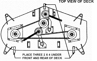
FIGURE 4.6
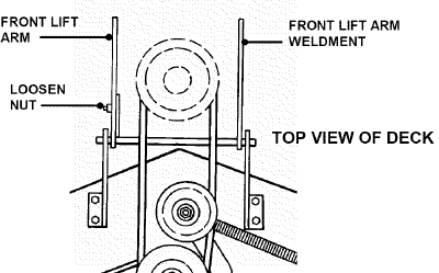
FIGURE 4.7
WARNING DO NOT attempt any adjustments, maintenance or service with the engine or blades running. STOP blades. STOP engine. Set brake. Remove key. Remove spark plug wire from spark plug and secure wire away from spark plug. Engine and components can be extremely hot. Avoid burns by allowing engine and components sufficient time to cool.
4.2.6. MOWER DECK ADJUSTMENT (LEVELNESS) (FRONT To REAR)
Before making deck leveling adjustments, check the tire pressure. Add or release air as needed to bring pressure to 12 PSI in front and 12 PSI in rear tires. If tires are properly inflated and mowing is still uneven, check side-to-side deck levelness first then proceed to front to rear adjustment. Adjust front to rear deck levelness as follows:
1. Place machine on a smooth level surface.
2. Rotate outside blades so tips are pointed to the front and rear of deck. Measure the distance from blade tips to floor. The distance should be the same, or the rear no more than 1/4” higher than the front. If the rear blade tip is lower or is more than 1/4” higher than the front, proceed to next Step for adjustment.
3. Remove the hair pin & washer from swivel located on lift rod. Remove swivel/lift rod from hanger bracket.
4. Rotate swivel up or down to achieve the proper levelness.
5. Reinstall swivel/lift rod into hanger bracket. Reinstall washer & hair pin to secure swivel to hanger bracket. See Figure 4.8.
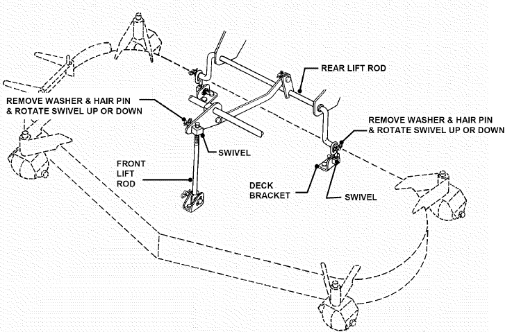
FIGURE 4.8
WARNING DO NOT attempt any adjustments, maintenance or service with the engine or blades running. STOP blades. STOP engine. Set brake. Remove key. Remove spark plug wire from spark plug and secure wire away from spark plug. Engine and components can be extremely hot. Avoid burns by allowing engine and components sufficient time to cool.
4.3 TRACTOR DRIVE COMPONENTS
4.3.1. BRAKE ADJUSTMENT
When adjusted properly, the brake should stop the tractor in approximately 6 feet or less from top speed. Drive the machine at maximum forward speed and apply the brake. If stopping distance is greater than 6 feet, brake adjustment is required.
1. Turn engine “OFF”. Remove key.
2. Locate brake adjustment nut underneath the left side at the rear of tractor. See Figure 4.9.
3. Turn nut 1 turn clockwise to increase braking action. DO NOT over tighten brake adjustment.
4. Start engine and test brake.
5. Continue adjustment as described above until proper brake function is achieved.
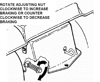
FIGURE 4.9
4.3.2. STEERING ADJUSTMENT
Should excessive “Play” be noted in the steering, adjust as follows:
1. Turn engine “OFF”. Remove key.
2. From left side of tractor, locate the steering sector below fuel tank. See Figure 4.10.
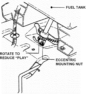
FIGURE 4.10
3. Loosen the eccentric mounting nut and rotate the eccentric clockwise until steering “Play” is reduced. See Figure 4.10.
4. Tighten eccentric mounting nut.
4.3.3. SHIFTER ADJUSTMENT
The shift linkage is set at the factory and should not require further adjustment. The shifter is adjusted properly when the speed control lever can be placed at rear edge of the neutral detent and the tractor remains absolutely stationary. If motion is detected, neutral adjustment will be required. DO NOT operate a machine that creeps when shifted to neutral.
1. Stop engine. Remove key.
2. Move speed control lever to rear edge of neutral detent and hold firmly.
3. Locate neutral adjustment nut underneath the right rear of the tractor. See Figure 4.11.
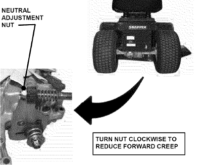
FIGURE 4.11
WARNING DO NOT attempt any adjustments, maintenance or service with the engine or blades running. STOP blades. STOP engine. Set brake. Remove key. Remove spark plug wire from spark plug and secure wire away from spark plug. Engine and components can be extremely hot. Avoid burns by allowing engine and components sufficient time to cool. Wear heavy leather gloves when handling or working around cutting blades. Blades are extremely sharp and can cause severe injury.
4. Turn the neutral adjustment nut 1/4 turn clockwise to reduce FORWARD creep. Turn the adjustment nut 1/4 turn counter clockwise to reduce Reverse creep. Only turn the adjustment nut in 1/4 turn increments.
5. Check for creep in neutral. Start engine. Move speed control lever to rear edge of the neutral detent. Machine should not move. If further adjustment is required, stop engine and repeat Step 4.
4.3.4. TRACTION DRIVE BELT ADJUSTMENT
Should a gradual loss of traction be noticed, it may be necessary to adjust the traction drive belt tension. Adjust as follows:
1. Move tractor to a firm, level surface.
2. Turn engine "OFF". Remove key.
3. Remove mowing deck.
4. Remove the traction drive belt stationary idler mounting bolt. See Figure 4.12.
5. Move the stationary idler one hole towards right side of tractor for more belt tension.
NOTE: Note the orientation of belt guide and make certain it remains in the same orientation after moving idler. Should less tension be required move stationary idler towards right side of tractor. See Figure 4.12.
6. Secure stationary idler with mounting bolt.
7. Place spark plug wire onto spark plug. Set park brake. Start engine.
8. Visually inspect traction drive belt for movement. When properly adjusted, the traction drive belt should not have any movement or rotation with the engine running and park brake engaged.
9. Should movement be present, readjust traction drive belt to release belt tension as described in previous instructions.
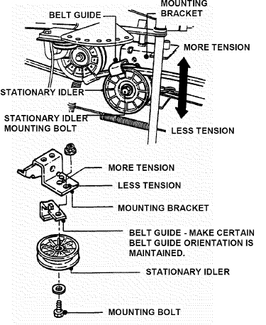
FIGURE 4.12
4.4 MOWER BLADE SERVICE
4.4.1. (STANDARD) BLADE WEAR LIMITS
All mower blades should be checked for excessive wear and damage before each use. See Figure 4.13.
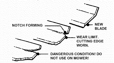
FIGURE 4.13
WARNING DO NOT attempt any adjustments, maintenance or service with the engine or blades running. STOP blades. STOP engine. Set brake. Remove key. Remove spark plug wire from spark plug and secure wire away from spark plug. Engine and components can be extremely hot. Avoid burns by allowing engine and components sufficient time to cool. Wear heavy leather gloves when handling or working around cutting blades. Blades are extremely sharp and can cause severe injury.
4.4.2. (NINJA) BLADE WEAR LIMITS
The ninja recycling blade requires more frequent service intervals than standard blades. Check for excessive wear and damage before each use. See Figure 4.14.
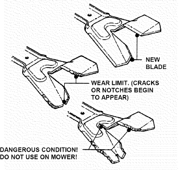
FIGURE 4.14
4.4.3. (STANDARD) BLADE SHARPENING
Blades should be kept sharp at all times. When the blades are dull, cut grass will be ragged and lawn will usually turn brown. Sharpen standard blades as follows:
1. Move tractor to a firm, level surface.
2. Turn engine "OFF". Remove key.
3. Remove mowing deck from tractor.
4. Remove mower blade(s).
5. If a blade is in good condition, sharpen cutting edge at an angle of 22 to 28 degrees. DO NOT sharpen beyond existing cutting edge. Replace blades not in good condition. See Figure 4.15.
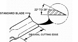
FIGURE 4.15
4.4.4. (NINJA) BLADE SHARPENING
The Ninja recycling blades requires more frequent service intervals than standard blades. When the blades are dull, cut grass will be ragged and lawn will usually turn brown. Sharpen standard blades as follows:
1. Move tractor to a firm, level surface.
2. Turn engine "OFF". Remove key.
3. Remove mowing deck from tractor.
4. Remove mower blade(s).
5. Sharpen all cutting edges of the Ninja recycling blade at an angle of 22 to 28 degrees for optimum performance. See Figure 4.16.
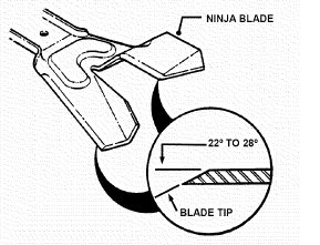
FIGURE 4.16
WARNING DO NOT attempt any adjustments, maintenance or service with the engine or blades running. STOP blades. STOP engine. Set brake. Remove key. Remove spark plug wire from spark plug and secure wire away from spark plug. Engine and components can be extremely hot. Avoid burns by allowing engine and components sufficient time to cool. Wear heavy leather gloves when handling or working around cutting blades. Blades are extremely sharp and can cause severe injury.
4.4.5. 42" & 48” MOWER BLADE REPLACEMENT
1. Move tractor to a firm, level surface.
2. Turn engine "OFF". Remove key.
3. Remove mowing deck from tractor.
4. Position deck on its left side to access blade.
5. Remove blade mounting bolts on 42” decks or nuts on 48” decks. See Figure 4.17.
6. Install new blade.
7. Torque 30 to 40 ft lbs. for 42” Deck.
Torque 80 to 90 ft lbs. for 48” Deck.
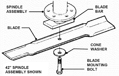
FIGURE 4.17
4.4.7. TRACTION DRIVE BELT REPLACEMENT 42” Mower Deck Removal
It is necessary to remove deck in order to replace belts. Remove deck as follows:
1. Place tractor on a firm, level surface such as a driveway or garage floor and set the park brake.
2. Turn engine “OFF”. Remove key.
3. Lower the deck to lowest setting.
4. Remove hair pin and washer securing front lift cable to front lift arm. See Figure 4.18.
5. Remove hair pins from the front deck hanger rod and slide out the rod from deck hanger bracket. Front lift arms will be now be disconnected. See Figure 4.19.
6. Hold front of deck "UP" and slide the front deck hanger rod to the right and out then lower the front of deck to the ground.
7. Remove deck drive belt from engine pulley bottom groove. See Figure 4.20.
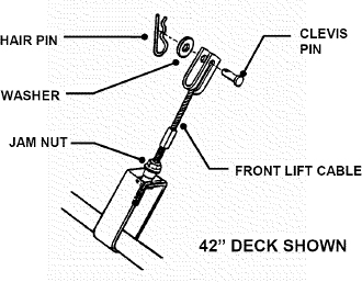
FIGURE 4.18
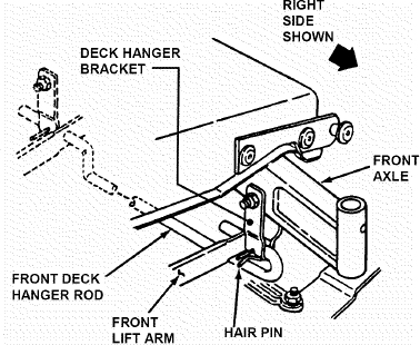
FIGURE 4.19
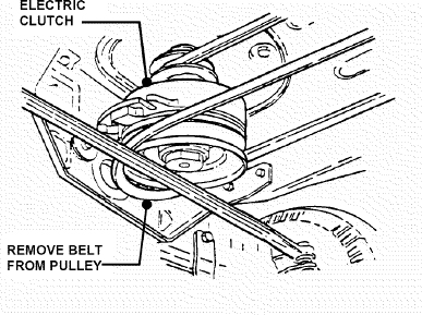
FIGURE 4.20
WARNING DO NOT attempt any adjustments, maintenance or service with the engine or blades running. STOP blades. STOP engine. Set brake. Remove key. Remove spark plug wire from spark plug and secure wire away from spark plug. Engine and components can be extremely hot. Avoid burns by allowing engine and components sufficient time to cool.
8. Remove hair pin and flat washer from rear deck hanger bracket on both sides of tractor.
9. Make note of hole used in sector plates.
10. Slide sector plates off of rear deck hanger brackets. See Figure 4.21.
11. Slide deck from underneath machine.
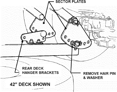
FIGURE 4.21
12. Disconnect traction belt idler pulley spring from tractor frame. See Figure 4.22.
13. Loosen mounting nuts on traction drive belt tension and stationary idlers just enough to allow belt to clear belt guides. See Figure 4.23.
14. Remove traction drive belt from engine pulley top groove. Remove belt from transmission pulley.
15. Remove traction drive belt.
Traction drive belt replacement
1. Place new traction drive belt over transmission pulley and span to engine pulley.
2. Place belt into top groove of engine pulley.
3. Route belt through stationary and tension idlers. See Figure 4.24.
4. Make certain belt is within belt guides of idlers.
5. Reattach tension idler spring to tractor frame.
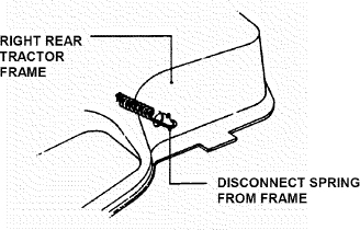
FIGURE 4.22
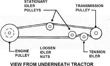
FIGURE 4.23
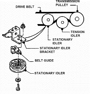
FIGURE 4.24
NOTE: When installing a new belt, make certain the stationary idler is mounted in the hole closest to the left hand side of the tractor.
6. Reinstall mower deck in reverse order of removal.
WARNING DO NOT attempt any adjustments, maintenance or service with the engine or blades running. STOP blades. STOP engine. Set brake. Remove key. Remove spark plug wire from spark plug and secure wire away from spark plug. Engine and components can be extremely hot. Avoid burns by allowing engine and components sufficient time to cool.
4.4.7. TRACTION DRIVE BELT REPLACEMENT 48” Mower Deck Removal
It is necessary to remove deck in order to replace belts. Remove deck as follows:
1. Place tractor on a firm, level surface such as a driveway or garage floor and set the park brake.
2. Turn engine “OFF”. Remove key.
3. Lower the deck to lowest setting.
4. Disconnect the front lift rod assembly from the front hanger bracket. See Figure 4.25.
5. Remove hair pins from the front deck hanger rod and slide out the rod from deck hanger bracket. Front lift arms will be now be disconnected. See Figure 4.26.
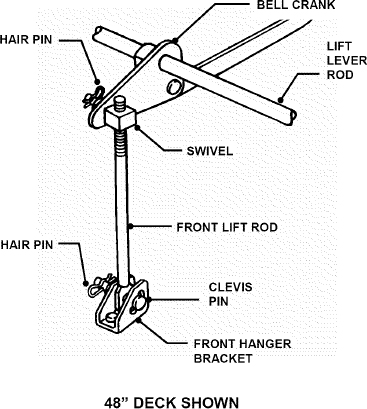
FIGURE 4.25
6. Turn the front wheels to the left.
7. Hold front of deck "UP" and slide the front deck hanger rod to the right and out then lower the front of deck to the ground.
8. Remove deck drive belt from engine pulley bottom groove. See Figure 4.27.
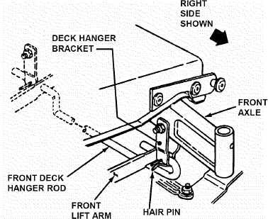
FIGURE 4.26
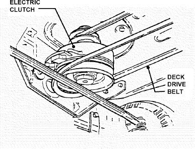
FIGURE 4.27
WARNING DO NOT attempt any adjustments, maintenance or service with the engine or blades running. STOP blades. STOP engine. Set brake. Remove key. Remove spark plug wire from spark plug and secure wire away from spark plug. Engine and components can be extremely hot. Avoid burns by allowing engine and components sufficient time to cool.
9. Remove hair pin and flat washer from rear deck hanger bracket on both sides of tractor.
10. Make note of hole used in sector plates.
11. Slide sector plates off of rear deck hanger brackets. See Figure 4.28.
12. Slide deck from underneath machine.
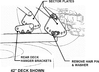
FIGURE 4.28
13. Disconnect traction belt idler pulley spring from tractor frame. See Figure 4.29.
14. Loosen mounting nuts on traction drive belt tension and stationary idlers just enough to allow belt to clear belt guides. See Figure 4.30.
15. Remove traction drive belt from engine pulley top groove. Remove belt from transmission pulley.
16. Remove traction drive belt.
Traction drive belt replacement
1. Place new traction drive belt over transmission pulley and span to engine pulley.
2. Place belt into top groove of engine pulley.
3. Route belt through stationary and tension idlers. See Figure 4.31.
4. Make certain belt is within belt guides of idlers.
5. Attach tension idler spring to tractor frame.
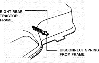
FIGURE 4.29
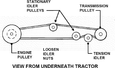
FIGURE 4.30
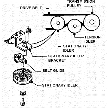
FIGURE 4.31
NOTE: When installing a new belt, make certain the stationary idler is mounted in the hole closest to the left hand side of the tractor.
6. Reinstall mower deck in reverse order of removal.
WARNING DO NOT attempt any adjustments, maintenance or service with the engine or blades running. STOP blades. STOP engine. Set brake. Remove key. Remove spark plug wire from spark plug and secure wire away from spark plug. Engine and components can be extremely hot. Avoid burns by allowing engine and components sufficient time to cool.
4.4.8. DECK BELT REMOVAL & REPLACEMENT 42" Deck Drive Belt
1. Place tractor on a firm level surface.
2. Turn engine "OFF". Remove key.
3. Remove mower deck. Refer to Section “DECK REMOVAL”.
4. Remove deck idler tension spring. Loosen bolts that secure the end of the spindle pulley covers and rotate cover around out of the way. See Figure 4.32 & Figure 4.33.
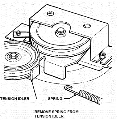
FIGURE 4.32
5. Remove old belt.
6. Replace with new belt.
7. Reinstall both pulley covers.
8. Reinstall mower deck to tractor.
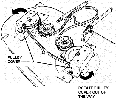
FIGURE 4.33
9. Adjust idler pulley belt guide if necessary to obtain 1/16" clearance between belt and belt guide. See Figure 4.34.
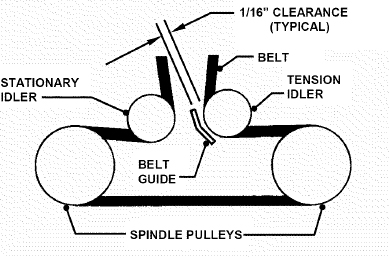
FIGURE 4.34
WARNING DO NOT attempt any adjustments, maintenance or service with the engine or blades running. STOP blades. STOP engine. Set brake. Remove key. Remove spark plug wire from spark plug and secure wire away from spark plug. Engine and components can be extremely hot. Avoid burns by allowing engine and components sufficient time to cool.
4.4.8. DECK BELT REMOVAL & REPLACEMENT 48" Deck Drive Belt
1. Place tractor on a firm level surface.
2. Turn engine "OFF". Remove key.
3. Remove mower deck. See Section on DECK REMOVAL.
4. Remove deck idler tension spring. Remove nuts that secure the spindle pulley covers. See Figure 4.35.
5. Remove belt.
6. Install new belt.
7. Reinstall both pulley covers.
8. Reinstall mower deck to tractor.
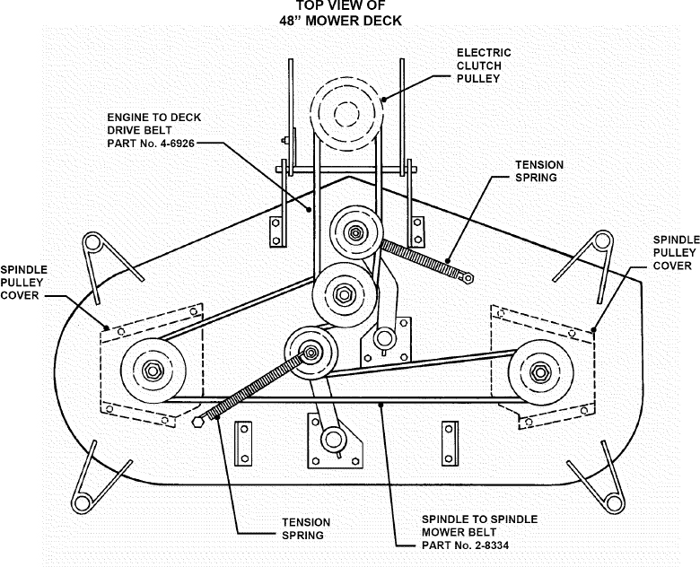
FIGURE 4.35
WARNING DO NOT attempt any adjustments, maintenance or service with the engine or blades running. STOP blades. STOP engine. Set brake. Remove key. Remove spark plug wire from spark plug and secure wire away from spark plug. Engine and components can be extremely hot. Avoid burns by allowing engine and components sufficient time to cool.
4.5 BATTERY
NOTE: The battery in this machine is maintenance-free. It has been filled to the proper level with acid and is sealed. Do not attempt to open battery.
4.5.1. BATTERY REMOVAL
1. Raise operator's seat.
2. Remove the two adjusting knobs.
3. Remove seat assembly and move forward. Use care not to disconnect wires from seat switch. See Figure 4.36.
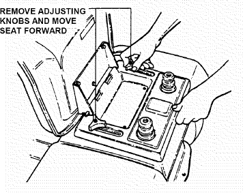
FIGURE 4.36
4. Remove negative ( - ) cable first.
5. Remove positive ( + ) cable last.
6. Remove battery. See Figure 4.37.
WARNING Cables must be connected to battery terminals in the proper position as shown. DO NOT attempt to charge battery while installed on tractor. DO NOT use "BOOST" chargers on the battery. If battery is removed, DO NOT operate engine without insulating Positive + battery cable terminal with electrical tape, or sparking from battery cables can result.
4.5.2. BATTERY INSTALLATION
1. Slide battery into battery housing.
2. Connect positive (+) cable first.
3. Connect negative (-) cable last.
4. Reinstall seat assembly. Use care not to disconnect wires from seat switch.
5. Reinstall the two adjusting knobs.
6. Lower operator's seat.
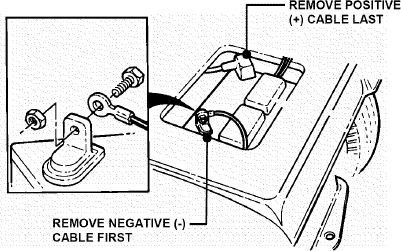
FIGURE 4.37
WARNING Keep all sparks, flame and fire away from area when charging battery.
4.5.3. BATTERY CHARGING
1. Remove battery. Refer to Section “BATTERY REMOVAL”.
2. Place battery in a well ventilated area on a level, non-concrete surface.
3. Connect battery charger to battery terminals. (NOTE: Always connect red cable to positive (+) terminal and black cable to negative (-) terminal.)
4. Charge battery at 6-10 amps for 1 hour.
5. If battery will not accept charge, or is partially charged after 1 hour of charging, replace with new battery.
4.5.4. BATTERY STORAGE
When out of season, it is recommended the battery be removed, charged and stored.
1. Remove battery. Refer to Section “BATTERY REMOVAL”.
2. Bring battery to full charge, if required.
3. Store battery in an area away from the RIDER on a wood surface. DO NOT STORE BATTERY ON A CONCRETE SURFACE.
WARNING Never attempt to charge the battery while it is installed on the machine. DO NOT use “BOOST” chargers on the battery.
4.5.5. BATTERY TESTING
1. Remove battery. Refer to section “BATTERY REMOVAL”.
2. Using a voltmeter, check the battery’s state of charge by comparing the voltmeter reading with the chart below. (Remember to hook the positive (red) lead of the voltmeter to the battery’s positive terminal, and the negative lead to the negative terminal.)
| Battery Condition Chart | |
|---|---|
| State of Charge | Digital Voltmeter |
| 100% Charged w/ Sulfate Stop | 12.80v |
| 100% Charged | 12.60v |
| 75% Charged | 12.40v |
| 50% Charged | 12.10v |
| 25% Charged | 11,90v |
| 0% Charged | Less than 11.80v |
4.5.6. NEW BATTERY PREPARATION
1. Remove battery from carton.
2. Place battery in a well ventilated area on a level, non-concrete surface.
3. Check date on battery label. If battery is placed into service after the date shown, charge battery. Refer to section “BATTERY CHARGING”.
4. After charging (if required), slide battery partially into battery housing.
5. Connect positive (+) cable (red) first, from wiring harness to the positive terminal (+) on battery using bolt and nut provided in hardware bag. Connect negative (-) cable (black) last, to negative terminal (-) on battery using bolt and nut. Apply a small amount of grease over terminals to prevent corrosion.
6. Insert battery completely into battery housing.
7. Reinstall seat assembly.
WARNING Shield the positive terminal with terminal cover located on battery harness. This prevents metal from touching the positive terminal, which could cause sparks. Cables must be connected to battery terminals in the proper position. RED (Positive) cable must go to the ( + ) terminal. BLACK (Negative) cable must go to the (-) terminal.
AVAILABLE ACCESSORIES
The SNAPPER LAWN TRACTOR can be equipped with a variety of accessories that increase its versatility. The accessories available for each model are listed in the chart below. Contact an authorized SNAPPER dealer for ordering any of the accessories desired.
| AVAILABLE ACCESSORIES | LT160H42IBV LT180H42IBV2 | LT200H48IBV2 |
|---|---|---|
| Thatcherizer | 6-1247 | 6-1247 |
| Dethatcher | 6-1912 | 6-1912 |
| Lawn Sweeper Dethatcher | 6-1914 | 6-1914 |
| Lawn Sweeper | 6-1913 | 6-1913 |
| Aerator | 6-1911 | 6-1911 |
| Broadcast Spreader | 6-1916 | 6-1916 |
| Lawn Roller | 6-1915 | 6-1915 |
| 42” Snow Blade* | 6-1352 | N/A |
| 46” Dozer Blade Spring Trip**** | 6-1881 | 6-1881 |
| Dozer Blade Support Kit | 6-1370 | 6-1370 |
| 40” Snow Thrower**** | 6-1880 | N/A |
| Debris Blower**** | 6-1883 | N/A |
| RAD Quick Hitch/Subframe Kit | 6-1879 | N/A |
| Rear Weight Kit | 6-1245 | 6-1245 |
| Tire Chains | (1)6-1399 / (2) 6-1333 | 6-1333 |
| Ninja Recycling/Mulch Kit | 6-1987 | NA |
| 48” Wave Recycling/Mulch Kit | NA | 6-3110 |
| Single Bag Catcher***† | 6-0944 | NA |
| Adapter Mounting Kit | 6-1334 | 6-1334 |
| Utility Trailer | 6-1910 | 6-1910 |
| Front Bumper | 6-1982 | 6-1982 |
* Requires Dozer Blade Support Kit ***Requires Adapter Mounting Kit
** Requires Snow Thrower Support Kit ****Requires Hitch/Subframe Kit
WARNING † Grass Catcher bags used on SNAPPER products are made of woven fabric, and are subject to deterioration and wear during normal usage. Check condition of bags before each use. Immediately replace worn or damaged catcher bags with only bags recommended by SNAPPER. The Grass Catcher is optional equipment on some models.
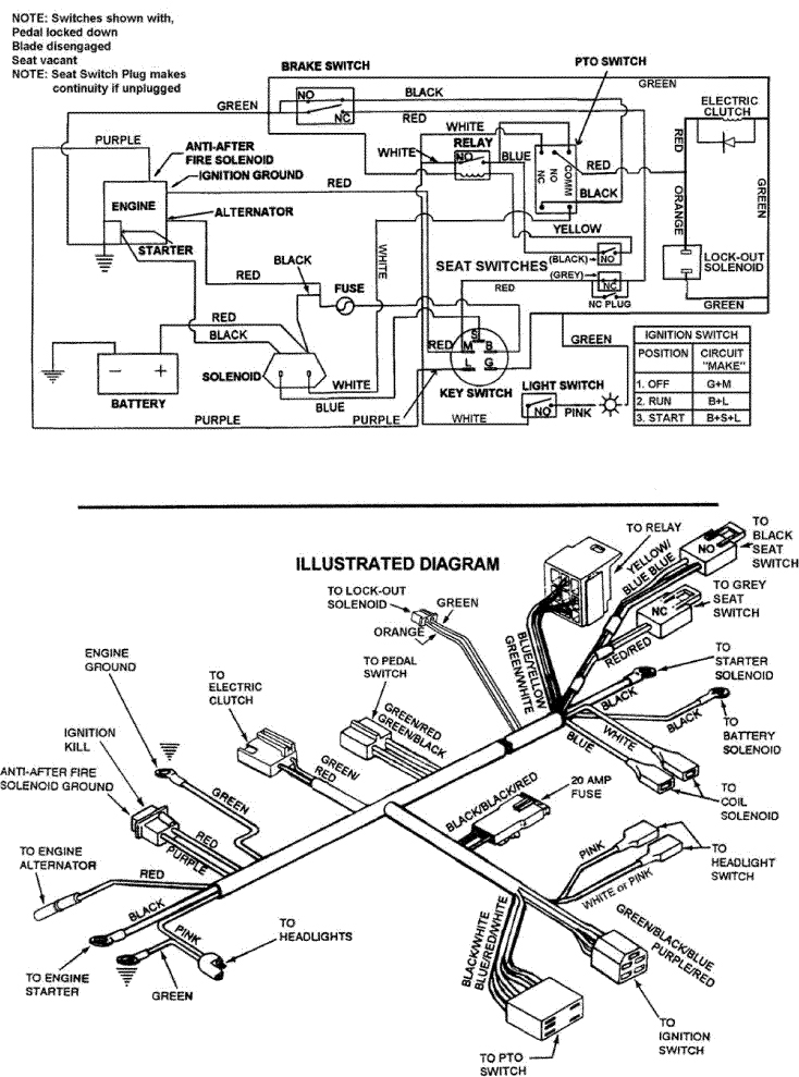
SECTION 5 - ELECTRICAL SYSTEM
ELECTRICAL - B & S TWIN CYLINDER ENGINE
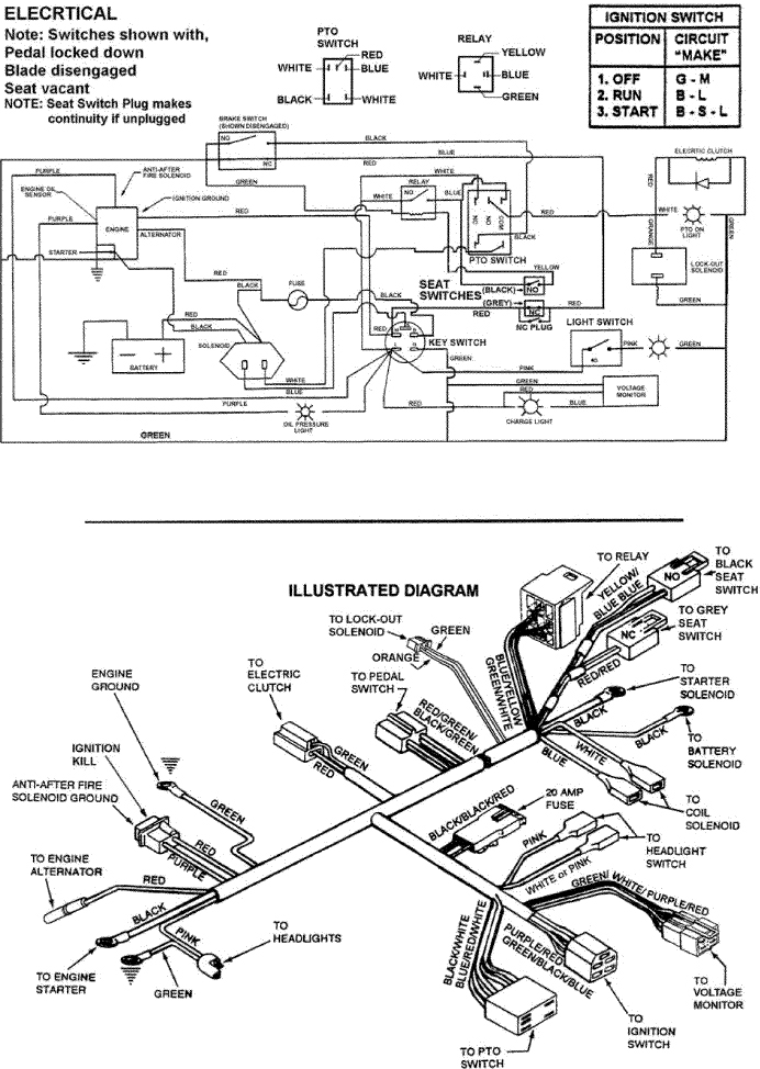
ELECTRICAL - B & S SINGLE CYLINDER ENGINE
TROUBLESHOOTING GUIDE
| PROBLEM | PROBABLE CAUSE | CORRECTIVE ACTION |
|---|---|---|
| Starter Will Not Crank Engine | 1. Battery dead. | 1. Service battery. |
| 2. Blown fuse. | 2. Replace fuse. | |
| 3. Electrical connections loose or corroded. | 3. Clean and check connections for good contact. | |
| 4. Defective ignition switch. | 4. Contact authorized SNAPPER dealer. | |
| 5. Starter Spins without engaging. | 5. Release Start key and repeat attempt. If starter continues to spin contact Engine Dealer. | |
| Engine Will Not Start | 1. Blade engagement switch in the “ON” position. | 1. Move blade engagement switch to “OFF”. |
| 2. Park brake not set. | 2. Set park brake. | |
| 3. Fuel tank empty. | 3. Fill fuel tank with fresh fuel. | |
| 4. Engine needs choking. | 4. Move engine speed control to “CHOKE”. | |
| 5. Spark plug wire disconnected. | 5. Place spark plug wire onto spark plug. | |
| 6. Battery weak or dead. | 6. Service battery. | |
| 7. Faulty interlock switch. | 7. Contact authorized SNAPPER dealer. | |
| Engine Stalls After Running | 1. Operator not in seat. | 1. Sit in operator’s seat. |
| 2. Engine speed control in the “CHOKE” position. | 2. Move engine speed control to “FAST”. | |
| 3. Fuel tank empty. | 3. Fill with fuel to proper level. | |
| 4. Engine air pre-cleaner and or air cleaner dirty. | 4. Clean free of all debris. | |
| 5. Spark plug defective or gap set improperly. | 5. Service spark plug. | |
| 6. Fuel filter stopped up. | 6. Replace fuel filter. | |
| 7. Water, debris or stale fuel in fuel system. | 7. Drain and clean fuel system. | |
| Engine Loses Power | 1. Excessive load on engine. | 1. Lessen load by slowing ground speed. |
| 2. Engine air pre-cleaner or air cleaner dirty. | 2. Clean or replace filters. | |
| 3. Engine oil level low. | 3. Fill with engine oil to proper level. | |
| 4. Engine cooling fins and air screens excessively dirty. | 4. Clean free of all debris. | |
| 5. Spark plug faulty. | 5. Service spark plug. | |
| 6. Water, debris or stale fuel in fuel system. | 6. Drain and clean fuel system. | |
| Engine Backfires When Turned To “STOP” | 1. Engine speed control set too “FAST”. | 1. Set engine speed control to “SLOW” and allow engine to idle. Then, turn key to “OFF”. |
| Excessive Vibration | 1. Damaged or bent mower blades. | 1. Service mower blade(s). |
| 2. Loose blade components. | 2. Service and tighten loose parts. | |
| 3. Loose or missing air lift (if equipped). | 3. Replace air lifts. Tighten to proper torque. | |
| Tractor Will Not Move Or Loss Of Ground Speed | 1. Speed control handle in the neutral “N” position. | 1. Place speed control in desired speed. |
| 2. Roll release control in “ROLL” position. | 2. Move roll release control to the engaged position. | |
| 3. Shifter out of adjustment. | 3. Adjust shifter. | |
| 4. Traction drive belt requires adjustment. | 4. Adjust traction drive belt. | |
| 5. Traction drive belt requires replacement. | 5. Replace traction drive belt. | |
| Blade(s) Not Turning | 1. Blade engagement switch in the “OFF” position. | 1. Move switch to the “ON” position. |
| 2. Blade belt requires adjustment. | 2. Adjust mower belt. | |
| 3. Blade belt requires replacement. | 3. Replace mower belt. | |
| 4. Electric clutch not functioning. | 4. Contact authorized SNAPPER dealer. | |
| Cutting Grass Improperly | 1. Uneven tire pressure. | 1. Bring to proper pressure. |
| 2. Cutting height too low or high. | 2. Adjust cutting height. | |
| 3. Engine speed too slow. | 3. Move engine speed control to “FAST”. | |
| 4. Forward speed too fast. | 4. Move speed control to a slower speed. | |
| 5. Deck side to side level requires adjustment. | 5. Adjust side to side level. | |
| 6. Deck front to rear level requires adjustment. | 6. Adjust front to rear level. | |
| 7. Cutting Blade dull or damaged. | 7. Sharpen cutting edges or replace blade. | |
| 8. Blade belt requires replacement. | 8. Replace blade belt. | |
| 9. Blade belt slipping. | 9. Replace blade belt. | |
| Poor Grass Discharge | 1. Engine speed too slow. | 1. Move engine speed control to “FAST”. |
| 2. Forward speed too fast. | 2. Move speed control to a slower speed. | |
| 3. Grass is wet. | 3. Mow when grass is dry. | |
| 4. Excessively worn or damaged blade(s). | 4. Service mower blade(s). | |
| 5. Build up of grass clippings and debris under deck. | 5. Clean deck. | |
| 6. Improper blade(s) installed on deck. | 6. Install proper SNAPPER blades. | |
| 7. Blade(s) installed improperly on deck. | 7. Install blades properly. | |
| Battery Will Not Charge | 1. Poor cable connections. | 1. Clean cables and battery terminals. |
| 2. Bad battery cell(s). | 2. Replace with new battery. | |
| 3. Faulty alternator. | 3. Contact engine manufacturer’s dealer. | |
| Transmission | 1. Leaking axle seats. | 1. Contact authorized SNAPPER dealer. |
| 2. Leaking at casing seal. | 2. Contact authorized SNAPPER dealer. |
MAINTENANCE SCHEDULE
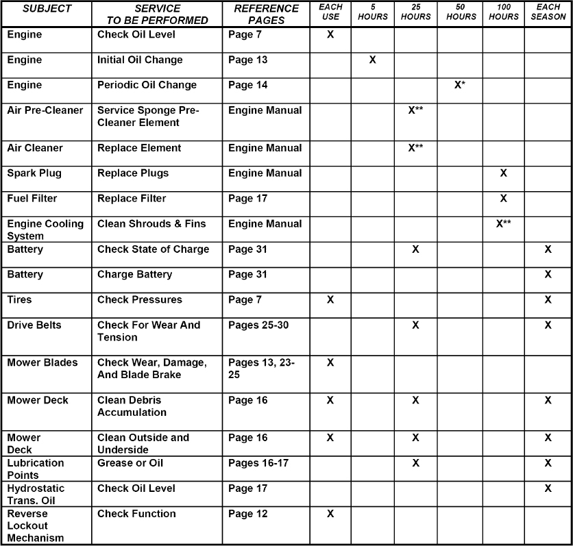
*Change oil every 25 hours when operating under heavy load or high temperatures.
**Clean more often under dusty conditions or when air debris is present
MAINTENANCE PARTS
| TRACTOR | DRIVE BELTS | MOWER BLADES | |||
|---|---|---|---|---|---|
| MODEL No. | Engine to Transmission | Engine to Deck | Spindle to Spindle | Standard | NINJA |
| LT160H42IBV | 7-3834 | 7-2349 | - | 2-6691 | 2-6407 |
| LT180H42IBV2 | 7-3834 | 7-2349 | 2-6691 | 2-6407 | |
| LT200H48IBV2 | 7-3834 | 7-5121 | 2-8334 | 2-9247 | … |
SNAPPER®
2 YEAR LIMITED WARRANTY
For two (2) years from purchase date for the original purchaser’s residential, non-commercial use, SNAPPER, through any authorized SNAPPER dealer will replace, free of charge (except for taxes where applicable), any part or parts found upon examination by the factory at McDonough, Georgia, to be defective in material or workmanship or both.
For ninety (90) days from purchase date for the original purchaser’s commercial, rental, or other non-residential use, SNAPPER, through any authorized SNAPPER dealer will replace, free of charge, any part or parts found upon examination by the factory at McDonough, Georgia, to be defective in material or workmanship or both.
All transportation costs incurred by the purchaser in submitting material to an authorized SNAPPER dealer for replacement under this warranty must be paid by the purchaser.
This warranty does not apply to certain transmissions, to engines and their components, and batteries, as these items are warranted separately. This warranty does not apply to parts that have been damaged by accident, alteration, abuse, improper lubrication, normal wear, or other cause beyond the control of SNAPPER. This warranty does not cover any machine or component part that has been altered or modified changing safety, performance, or durability.
Batteries have a one (1) year warranty period with free replacement if required for one (1) year from the original purchase date. SNAPPER will not be responsible for any installation cost incurred. The battery warranty only covers original equipment batteries and does not cover damage to the battery or machine caused by neglect or abuse, destruction by fire, explosion, freezing, overcharging, or improper maintenance.
There is no other express warranty.
DISCLAIMER OF WARRANTY
Implied warranties, including those of merchantability and fitness for a particular purpose, are limited to two (2) years from purchase date for the original purchaser’s residential or other non-commercial use, and ninety (90) days from purchase for the original purchaser’s commercial, rental or other non-residential use, and to the extent permitted by law, any and all implied warranties are excluded. This is the exclusive remedy. Liabilities for consequential damages, under any and all warranties are excluded.
Some states do not allow limitations on how long an implied warranty lasts, or do not allow the exclusion or limitation of incidental or consequential damages, so the above limitation or exclusion may not apply to you.
This warranty gives you specific legal rights, and you may also have other rights which vary from state to state.
WARNING: THE USE OF REPLACEMENT PARTS OTHER THAN GENUINE SNAPPER PARTS MAY IMPAIR THE SAFETY OF SNAPPER PRODUCTS AND WILL VOID ANY LIABILITY AND WARRANTY BY SNAPPER ASSOCIATED WITH THE USE OF SUCH PARTS.
IMPORTANT: Please fill out the attached SNAPPER Product Registration Card immediately and mail to:
Snapper’s Product Registration Center, P.O. Box 1379, McDonough, Georgia 30253
PRIMARY MAINTENANCE
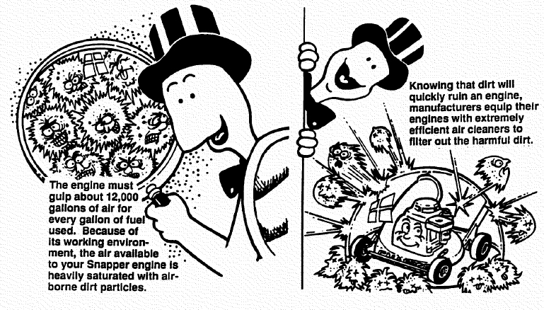
SNAPPER® vs. DIRT!

an illustration of how dirt can damage your engine & how reasonable maintenance can protect it!
Snapper uses the best available engines and components in their products in order to provide long, satisfactory service. However, proper care is essential in prolonging engine life. Dirt is your engine’s enemy number 1!


The engine on your Snapper product spends its entire life operating close to the ground at high speed creating a virtual storm of dust and dirt!
As the dirt particles are stopped, they build up and begin to clog the outside of the filter. This reduces the amount of air available to the engine and causes an over-rich fuel mixture which results in the following adverse effects:
An improperly serviced, dirt clogged air cleaner will:

- increase fuel consumption
- cause power loss
- result in hard starting
- create smoke from unburned fuel
- produce carbon build-up internally
- foul spark plug electrodes
- score cylinder walls
- burn valves
- wear out the engine pre-maturely
- COST YOU MONEY!
Damage caused by a poorly serviced air cleaner is not covered under the engine warranties. So, save yourself unnecessary expenses and undue aggravation by keeping the air cleaner properly serviced at the intervals specified in the engine owner’s manual.
It doesn’t take long to service an air cleaner. Follow the specific instructions in the engine owner’s manual for the type filter used. Prevent dirt from falling into the carburetor intake when servicing your air cleaner. Make sure components are installed in correct sequence after servicing to prevent unfiltered air from entering the engine. Some servicing hints on several common types are:

Generally, wash foam-type filters in a dishwashing detergent and water solution. Rinse and wring dry, then saturate with oil and squeeze out excess. Failure to re-oil this type filter will ruin the engine.
Clean paper elements by tapping lightly. Blowing with air will rupture paper elements.
Use a flashlight to detect clogged or torn paper elements - replace if damaged in any way.

Air is also needed to keep your engine cool. Dirt, dust & debris build up to restrict and clog cooling air intake screens and fins. Clean screens and fins at frequent intervals. The engine blower housing and shrouds should be removed at least once each season or more often under dry, dusty conditions for a thorough cleaning of fins.
Failure to keep external surfaces clean not only presents fire hazards, but causes overheating and resulting engine damages such as:
- distorted valve guides
- sticking valves
- scuffed, scored cylinder walls
- overspeeding
- loss of power
- complete failure of engine.

Dirt can also be introduced into an engine in dirty fuel from a contaminated container. Always use clean fresh fuel from a clean container to guard against dirt, sludge and water contamination.
Be aware that fuel breaks down in storage and forms gummy compounds which will block carburetor passages. Never use fuel more than 3 months old. Drain tank then run the engine out of fuel before storing during the off-season.


An engine must also have proper lubrication. All engines use some oil. On 4-cycle engines, CHECK OIL LEVEL BEFORE EACH START-UP. Wipe area clean around the oil check plug or dipstick opening to keep dirt from falling into the engine when checking the oil. Always check with the machine on a level surface. On engines with dipstick, keep the level up to, but not over, the FULL mark. When adding oil, allow time for all of the oil to flow down the fill tube to prevent a false full reading when the level could actually be low and result in engine damage.
On 4-cyle engines with an oil level plug, don’t be fooled into thinking the engine has sufficient lubricating oil if you can see “some” oil in the opening - the level should always be brought up to the point of overflowing at the top of the fill hole.
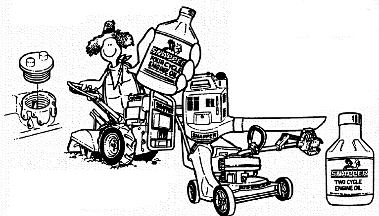
Change oil at regular intervals using a a high quality oil such as Snapper’s small engine formulated 4-cycle engine oil. Refer to the engine owner’s manual for oil details.
On 2-cycle engines, lubrication must be provided by an exact mixture of gasoline and 2-cycle air-cooled engine oil. A 2-cycle engine that is mistakenly run on straight gasoline will be ruined in less than 5 minutes! if you keep straight gasoline in addition to pre-mixed 2-cycle engine fuel, be sure the containers are clearly marked to avoid mix-up.
Snapper 2-cycle engines require a 32 to 1 mixture of gasoline and BIA certified TC-W oil such as Snapper’s 2-cycle engine oil. Many of the 2-cycle engine oils on the market today make fantastic claims, but for the best performance and long engine life, always use Snapper 2-cycle oil. Pre-mix the fuel and always shake the container before filling the tank.
STARTING CHECK LIST
| 1. | Engine Oil | • To full level (4-cycle) |
|---|---|---|
| • Properly mixed with gas (2 cycle) | ||
| 2. | Air Cleaner | • Clean and properly serviced |
| • Full fresh clean gasoline | ||
| 3. | Fuel Tank | • Fuel valve open |
| • Cap vent open | ||
| • Inline filter clean | ||
| 4. | Choke | • Operating properly |
| 5. | Primer (on some engines) | • Used properly |
| 6. | Safety Inter-lock Switches | • In proper position |
| • All wires properly connected | ||
| 7. | Switch & Blade Control | • Switch On |
| • Blade control properly positioned on walk mower | ||
| 8. | Spark plug | • Wire connected |
| • Good connection | ||
| 9. | Throttle control | • Start position |
| 10. | Blade | • Properly installed and torqued |
| • Sharpened | ||
| 11. | Muffler | • Good condition |
| • Not clogged | ||
| • Grass & leaves cleaned away |
Read and follow all safety instructions in safety booklets and manuals.

Keep in mind that dirt is your engine’s enemy #1 both internally and externally! internally, dirt will quickly ruin an engine and externally it will cause overheating and resulting internal .damages. Damage caused by improper lubrication, poor air cleaner service or overheating due to dirt cannot be covered under warranty.
It only takes a few moments to service the engine (and equipment) on a routine basis but the rewards will be a quick starting, responsive engine that will provide long satisfactory service with minimum maintenance cost. The prestart checklist in the next column and instructions in your Snapper Operator’s Manual are designated to help you keep your Snapper in top operating condition with minimum effort!
SNAPPER PRODUCT REGISTRATION FORM
IMPORTANT: KEEP THIS INFORMATION FOR YOUR PERSONAL RECORDS
(Complete the following information on your Snapper purchase)
Model Number __________________________________________
Serial Number __________________________________________
Date of Purchase _______________________________________
Retailer _______________________________________________
Retailer's Phone Number ________________________________
It is very important that you register your purchase with Snapper to ensure warranty coverage. Please mail your product registration card to:
Snapper at P.O. Box 777, McDonough, Georgia 30253.
Or you may register on line at www.snapper.com.
You can contact us at our web site or if you would like to speak with a Customer Service Representative. Call us at the Snapper Customer Relations Center. For faster service please have your Serial Number and Model Number available.
Call the Snapper Customer Relations Center at 1-800-935-2967.
SERVICE NOTES


Parts & More
Bench Grinder
Front-Engine Lawn Tractor
Gas Chainsaw
Gas Leaf Blower
Gas Range
Gas Snowblower
Gas Walk-Behind Mower
Hole Digger
Log Splitter
Parts
Side-By-Side Refrigerator
Washer