- Kenmore refrigerator water filters
- Whirlpool refrigerator water filters
- Samsung refrigerator water filters
- GE refrigerator water filters
- LG refrigerator water filters
- Frigidaire refrigerator water filters
- KitchenAid refrigerator water filters
- Maytag refrigerator water filters
- Kenmore Elite refrigerator water filters
- Estate refrigerator water filters
- GE Profile refrigerator water filters
- Amana refrigerator water filters
- Bosch refrigerator water filters
- Dacor refrigerator water filters
- Electrolux refrigerator water filters
Top DIY repair help
View All Repair Categories
Appliances
Lawn & Garden
Power Tools
Home Improvement
Sports & Leisure
Heating & Cooling
MTD 31AS62EE799 gas snowblower manual
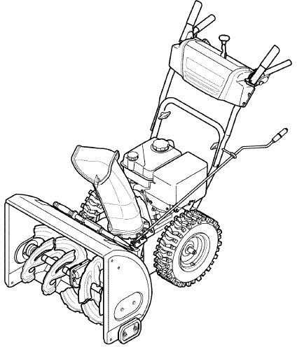
Are you looking for information on using the MTD 31AS62EE799 gas snowblower? This user manual contains important warranty, safety, and product feature information. View the user manual below for more details. Want a copy for yourself? Download or print a free copy of the user manual below.
SNOW THROWER (OWNERS) 769-05095D 72611(viewing)Download PDF
Operator’s Manual
![]()
24” SNOW THROWER
Model No. 247.889571
CAUTION: Before using
this product, read this
manual and follow all
safety rules and operating
instructions.
this product, read this
manual and follow all
safety rules and operating
instructions.
- SAFETY
- ASSEMBLY
- OPERATION
- MAINTENANCE
- PARTS LIST
- ESPAÑOL
Sears Brands Management Corporation, Hoffman Estates, IL 60179, U.S.A.
Visit our website: www.craftsman.com
FORM NO. 769-05095D
7/26/2011
TABLE OF CONTENTS
- Warranty Statement
- Safe Operation Practices
- Assembly Pages
- Operation
- Service &Maintenance
- Off-Season Storage
- Troubleshooting
- Parts List
- Repair Protection Agreement
- Español
WARRANTY STATEMENT
CRAFTSMAN TWO YEAR FULL WARRANTY
FOR TWO YEARS from the date of purchase, this product is warranted against any defects in material or workmanship. Defective product will receive free repair or free replacement if repair is unavailable.
This warranty is void if this product is ever used while providing commercial services or if rented to another person.
For warranty coverage details to obtain repair or replacement, visit the web site: www.craftsman.com
This warranty covers ONLY defects in material and workmanship. Warranty coverage does NOT include:
- Expendable items that can wear out from normal use within the warranty period, including but not limited to augers, auger paddles, drift cutters, skid shoes, shave plate, shear pins, spark plug, air cleaner, belts, and oil filter.
- Standard maintenance servicing, oil changes, or tune-ups.
- Tire replacement or repair caused by punctures from outside objects, such as nails, thorns, stumps, or glass.
- Tire or wheel replacement or repair resulting from normal wear, accident, or improper operation or maintenance.
- Repairs necessary because of operator abuse, including but not limited to damage caused by over-speeding the engine, or from impacting objects that bend the frame, auger shaft, etc.
- Repairs necessary because of operator negligence, including but not limited to, electrical and mechanical damage caused by improper storage, failure to use the proper grade and amount of engine oil, or failure to maintain the equipment according to the instructions contained in the operator’s manual.
- Engine (fuel system) cleaning or repairs caused by fuel determined to be contaminated or oxidized (stale). In general, fuel should be used within 30 days of its purchase date.
- Normal deterioration and wear of the exterior finishes, or product label replacement.
This warranty gives you specific legal rights, and you may also have other rights which vary from state to state.
Sears Brands Management Corporation, Hoffman Estates, IL 60179
PRODUCT SPECIFICATIONS
| Engine Oil Type: | 5W-30 |
|---|---|
| Engine Oil Capacity: | 20 ounces |
| Fuel Capacity: | 2.3 Quarts |
| Spark Plug: | F6RTC (951-10292) |
| Spark Plug Gap: | .020” to .030” |
MODEL NUMBER
Model Number .................................................................
Serial Number ..................................................................
Date of Purchase ...............................................................
Record the model number, serial number and date of purchase above
SAFETY INSTRUCTIONS
 WARNING
This symbol points out important safety instructions which, if not followed, could endanger the personal safety and/or property of yourself and others. Read and follow all instructions in this manual before attempting to operate this machine. Failure to comply with these instructions may result in personal injury. When you see this symbol, HEED ITS WARNING!
WARNINGCALIFORNIA PROPOSITION 65
Engine Exhaust, some of its constituents, and certain vehicle components contain or emit chemicals known to State of California to cause cancer and birth defects or other reproductive harm.
DANGERThis machine was built to be operated according to the safe operation practices in this manual. As with any type of power equipment, carelessness or error on the part of the operator can result in serious injury. This machine is capable of amputating fingers, hands, toes and feet and throwing debris. Failure to observe the following safety instructions could result in serious injury or death.
WARNINGYour Responsibility— Restrict the use of this power machine to persons who read, understand and follow the warnings and instructions in this manual and on the machine.
SAVE THESE INSTRUCTIONS!
TRAINING
- Read, understand, and follow all instructions on the machine and in the manual(s) before attempting to assemble and operate. Failure to do so can result in serious injury to the operator and/or bystanders. Keep this manual in a safe place for future and regular reference and for ordering replacement parts.
- Be familiar with all controls and their proper operation. Know how to stop the machine and disengage them quickly.
- Never allow children under 14 years of age to operate this machine. Children 14 and over should read and understand the instructions and safe operation practices in this manual and on the machine and be trained and supervised by an adult.
- Never allow adults to operate this machine without proper instruction.
- Thrown objects can cause serious personal injury. Plan your snow-throwing pattern to avoid discharge of material toward roads, bystanders and the like.
- Keep bystanders, pets and children at least 75 feet from the machine while it is in operation. Stop machine if anyone enters the area.
- Exercise caution to avoid slipping or falling, especially when operating in reverse.
PREPARATION
Thoroughly inspect the area where the equipment is to be used. Remove all doormats, newspapers, sleds, boards, wires and other foreign objects, which could be tripped over or thrown by the auger/impeller.
- Always wear safety glasses or eye shields during operation and while performing an adjustment or repair to protect your eyes. Thrown objects which ricochet can cause serious injury to the eyes.
- Do not operate without wearing adequate winter outer garments. Do not wear jewelry, long scarves or other loose clothing, which could become entangled in moving parts. Wear footwear which will improve footing on slippery surfaces.
- Use a grounded three-wire extension cord and receptacle for all machines with electric start engines.
- Disengage all control levers before starting the engine.
- Adjust collector housing height to clear gravel or crushed rock surfaces.
- Never attempt to make any adjustments while engine is running, except where specifically recommended in the operator’s manual.
- Let engine and machine adjust to outdoor temperature before starting to clear snow.
Safe Handling of Gasoline
To avoid personal injury or property damage use extreme care in handling gasoline. Gasoline is extremely flammable and the vapors are explosive. Serious personal injury can occur when gasoline is spilled on yourself or your clothes which can ignite. Wash your skin and change clothes immediately.
- Use only an approved gasoline container.
- Extinguish all cigarettes, cigars, pipes and other sources of ignition.
- Never fuel machine indoors.
- Never remove gas cap or add fuel while the engine is hot or running.
- Allow engine to cool at least two minutes before refueling.
- Never over fill fuel tank. Fill tank to no more than ½ inch below bottom of filler neck to provide space for fuel expansion.
- Replace gasoline cap and tighten securely.
- If gasoline is spilled, wipe it off the engine and equipment. Move machine to another area. Walt 5 minutes before starting the engine.
- Never store the machine or fuel container inside where there is an open flame, spark or pilot light (e.g. furnace, water heater, space heater, clothes dryer etc.).
- Allow machine to cool at least 5 minutes before storing.
- Never fill containers inside a vehicle or on a truck or trailer bed with a plastic liner. Always place containers on the ground away from your vehicle before filling.
- If possible, remove gas-powered equipment from the truck or trailer and refuel it on the ground. If this is not possible, then refuel such equipment on a trailer with a portable container, rather than from a gasoline dispenser nozzle.
- Keep the nozzle in contact with the rim of the fuel tank or container opening at all times until fueling is complete. Do not use a nozzle lock-open device.
OPERATION
- Do not put hands or feet near rotating parts, in the auger/impeller housing or chute assembly. Contact with the rotating parts can amputate hands and feet.
- The auger/impeller control lever is a safety device. Never bypass its operation. Doing so makes the machine unsafe and may cause personal injury.
- The control levers must operate easily in both directions and automatically return to the disengaged position when released.
- Never operate with a missing or damaged chute assembly. Keep all safety devices in place and working.
- Never run an engine indoors or in a poorly ventilated area. Engine exhaust contains carbon monoxide, an odorless and deadly gas.
- Do not operate machine while under the influence of alcohol or drugs.
- Muffler and engine become hot and can cause a burn. Do not touch. Keep children away.
- Exercise extreme caution when operating on or crossing gravel surfaces. Stay alert for hidden hazards or traffic.
- Exercise caution when changing direction and while operating on slopes. Do not operate on steep slopes.
- Plan your snow-throwing pattern to avoid discharge towards windows, walls, cars etc. Thus, avoiding possible property damage or personal injury caused by a ricochet.
- Never direct discharge at children, bystanders and pets or allow anyone in front of the machine.
- Do not overload machine capacity by attempting to clear snow at too fast of a rate.
- Never operate this machine without good visibility or light. Always be sure of your footing and keep a firm hold on the handles. Walk, never run.
- Disengage power to the auger/impeller when transporting or not in use.
- Never operate machine at high transport speeds on slippery surfaces. Look down and behind and use care when backing up.
- If the machine should start to vibrate abnormally, stop the engine, disconnect the spark plug wire and ground it against the engine. Inspect thoroughly for damage. Repair any damage before starting and operating.
- Disengage all control levers and stop engine before you leave the operating position (behind the handles). Walt until the auger/impeller comes to a complete stop before unclogging the chute assembly, making any adjustments, or inspections.
- Never put your hand in the discharge or collector openings. Do not unclog chute assembly while engine is running. Shut off engine and remain behind handles until all moving parts have stopped before unclogging.
- Use only attachments and accessories approved by the manufacturer (e.g. wheel weights, tire chains, cabs etc.).
- When starting engine, pull cord slowly until resistance is felt, then pull rapidly. Rapid retraction of starter cord (kickback) will pull hand and arm toward engine faster than you can let go. Broken bones, fractures, bruises or sprains could result.
- If situations occur which are not covered in this manual, use care and good judgment.
- For in-warranty safety, operation or maintenance questions, or to order parts and schedule service, call 1-800-4-MY-HOME.
CLEARING A CLOGGED DISCHARGE CHUTE
Hand contact with the rotating impeller inside the discharge chute is the most common cause of injury associated with snow throwers.
Never use your hand to clean out the discharge chute.
To clear the chute:
- SHUT THE ENGINE OFF!
- Wait 10 seconds to be sure the impeller blades have stopped rotating.
- Always use a clean-out tool, not your hands.
MAINTENANCE & STORAGE
- Never tamper with safety devices. Check their proper operation regularly. Refer to the maintenance and adjustment sections of this manual.
- Before cleaning, repairing, or inspecting machine disengage all control levers and stop the engine. Wait until the auger/impeller come to a complete stop. Disconnect the spark plug wire and ground against the engine to prevent unintended starting.
- Check bolts and screws for proper tightness at frequent intervals to keep the machine in safe working condition. Also, visually inspect machine for any damage.
- Do not change the engine governor setting or over-speed the engine. The governor controls the maximum safe operating speed of the engine.
- Snow thrower shave plates and skid shoes are subject to wear and damage. For your safety protection, frequently check all components and replace with original equipment manufacturer's (OEM) parts only as listed in the Parts pages of this operator's manual. Use of parts which do not meet the original equipment specifications may lead to improper performance and compromise safety!
- Check control levers periodically to verify they engage and disengage properly and adjust, if necessary. Refer to the adjustment section in this operator's manual for instructions.
- Maintain or replace safety and instruction labels, as necessary.
- Observe proper disposal laws and regulations for gas, oil, etc. to protect the environment.
- Prior to storing, run machine a few minutes to clear snow from machine and prevent freeze up of auger/impeller.
- Never store the machine or fuel container inside where there is an open flame, spark or pilot light such as a water heater, furnace, clothes dryer etc.
- Always refer to the operator's manual for proper instructions on off-season storage.
- Check fuel line, tank, cap, and fittings frequently for cracks or leaks. Replace if necessary.
- Do not crank engine with spark plug removed.
- According to the Consumer Products Safety Commission (CPSC) and the U.S. Environmental Protection Agency (EPA), this product has an Average Useful Life of seven (7) years, or 60 hours of operation. At the end of the Average Useful Life have the machine inspected annually by an authorized service dealer to ensure that all mechanical and safety systems are working properly and not worn excessively. Failure to do so can result in accidents, injuries or death.
DO NOT MODIFY ENGINE
To avoid serious injury or death, do not modify engine in any way. Tampering with the governor setting can lead to a runaway engine and cause it to operate at unsafe speeds. Never tamper with factory setting of engine governor.
NOTICE REGARDING EMISSIONS
Engines which are certified to comply with California and federal EPA emission regulations for SORE (Small Off Road Equipment) are certified to operate on regular unleaded gasoline, and may include the following emission control systems: Engine Modification (EM), Oxidizing Catalyst (OC), Secondary Air injection (SAI) and Three Way Catalyst (TWC) if so equipped.
SPARK ARRESTOR
WARNINGThis machine is equipped with an internal combustion engine and should not be used on or near any unimproved forest-covered, brush-covered or grass-covered land unless the engine’s exhaust system is equipped with a spark arrestor meeting applicable local or state laws (if any)
If a spark arrestor is used, it should be maintained in effective working order by the operator. in the State of California the above is required by law (Section 4442 of the California Public Resources Code). Other states may have similar laws. Federal laws apply on federal lands.
A spark arrestor for the muffler is available through your nearest Sears Parts and Repair Service Center.
SAFETY SYMBOLS
This page depicts and describes safety symbols that may appear on this product. Read, understand, and follow all instructions on the machine before attempting to assemble and operate.
| Symbol | Description |
|---|---|
 |
READ THE OPERATOR’S MANUAL(S) Read, understand, and follow all instructions in the manual(s) before attempting to assemble and operate |
 |
WARNING— ROTATING BLADES Keep hands out of in let and discharge openings while machine is running. There are rotating blades inside |
 |
WARNING— ROTATING BLADES Keep hands out of in let and discharge openings while machine is running. There are rotating blades inside |
 |
WARNING— ROTATING AUGER Do not put hands or feet near rotating parts, in the auger/impeller housing or chute assembly. Contact with the rotating parts can amputate hands and feet. |
 |
WARNING—THROWN OBJECTS This machine may pick up and throw objects which can cause serious personal injury. |
 |
WARNING—GASOLINE IS FLAMMABLE Allow the engine to cool at least two minutes before refueling. |
 |
WARNING— CARBON MONOXIDE Never run an engine indoors or in a poorly ventilated area. Engine exhaust contains carbon monoxide, an odorless and deadly gas. |
 |
WARNING— ELECTRICAL SHOCK Do not use the engine's electric starter in the rain |
ASSEMBLY
NOTE: References to right or left side of the snow thrower are determined from behind the unit in the operating position (standing directly behind the snow thrower, facing the handle panel).
REMOVING FROM CARTON
- Cut the comers of the carton and lay the sides flat on the ground. Remove and discard all packing inserts.
- Move the snow thrower out of the carton.
- Make certain the carton has been completely emptied before discarding it.
LOOSE PARTS
Two replacement auger shear pins are included in the handle panel. Refer to Replacing Shear Pins in the Operation section for more information regarding shear pin replacement.
ASSEMBLY
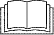
- Place the shift lever in the Forward-6 position.
- Observe the lower rear area of the snow thrower to be sure both cables are aligned with roller guides before pivoting the handle upward. See Figure 1.
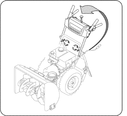
Figure 1
NOTE: Make certain the upper ends of each cable are seated properly in its bracket.
- Secure the handle by tightening the plastic wing knob located on both the left and right sides of the handle. See Figure 2. Remove and discard any rubber bands, if present. They are for packaging purposes only.
Figure 2
- Position the chute assembly over the base. See Figure 3.
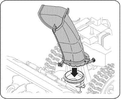
Figure 3
- Close the flange keepers to secure the chute assembly to the chute base. See Figure 4. The flange keepers will click into place when properly secure.
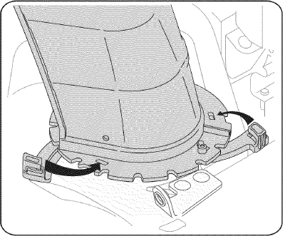
Figure 4
NOTE: If the flange keepers will not easily click into place, use the palm of your hand to apply swift, firm pressure to the back of each.
6.
- Remove the flat washer and hairpin clip from the end of the chute directional control.
- Insert the end of the chute directional control into the lower bracket and secure with the flat washer and hairpin clip just removed. See Figure 5. If necessary, the lower bracket can be adjusted. Refer to Chute Bracket Adjustment in the Service & Maintenance section.
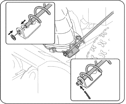
Figure 5
SET-UP
Chute Clean-Out Tool
A chute clean-out tool is fastened to the top of the auger housing with a mounting clip. See Figure 6. The tool is designed to clear a chute assembly of ice and snow. This item is fastened with a cable tie at the factory. Cut the cable tie before operating the snow thrower.
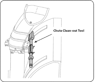
Figure 6
 WARNING
Never use your hands to clear a clogged chute assembly. Shut off engine and remain behind handles until all moving parts have stopped before using the clean-out tool to clear the chute assembly.
Tire Pressure
WARNINGUnder any circumstance do not exceed manufacturer's recommended psi. Equal tire pressure should be maintained at all times. Excessive pressure when seating beads may cause tire/rim assembly to burst with force sufficient to cause serious injury. Refer to sidewall of tire for recommended pressure.
The tires are over-inflated for shipping purposes. Check the tire pressure before operating the snow thrower. Refer to the tire side wall for tire manufacturer’s recommended psi and deflate (or inflate) the tires as necessary.
NOTE: Equal tire pressure is to be maintained at all times for performance purposes.
ADJUSTMENTS
Skid Shoes
The snow thrower skid shoes are adjusted upward at the factory for shipping purposes. Adjust them downward, if desired, prior to operating the snow thrower.
CAUTIONIt is not recommended that you operate this snow thrower on gravel as it can easily pick up and throw loose gravel, causing personal injury or damage to the snow thrower and surrounding property.
- For close snow removal on a smooth surface, raise skid shoes higher on the auger housing.
- Use a middle or lower position when the area to be cleared is uneven, such as a gravel driveway
NOTE: If you choose to operate the snow thrower on a gravel surface, keep the skid shoes in position for maximum clearance between the ground and the shave plate.
To adjust the skid shoes:
- Loosen the four hex nuts (two on each side) and carriage bolts. Move skid shoes to desired position. See Figure 7.
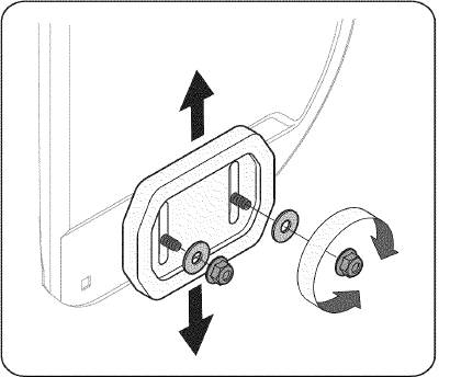
Figure 7
- Make certain the entire bottom surface of skid shoe is against the ground to avoid uneven wear on the skid shoes.
- Retighten nuts and bolts securely.
Chute Assembly
The distance snow is thrown can be adjusted by changing the angle of the chute assembly. To do so:
- Stop the engine by removing the ignition key and loosen the plastic wing knob found on the left side of the chute assembly.
- Pivot the chute upward or downward before retightening the wing knob. See Figure 8.
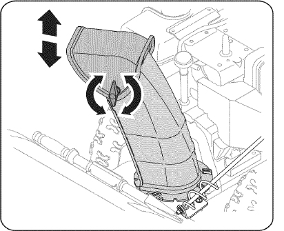
Figure 8
Auger Control
WARNINGPrior to operating your snow thrower, carefully read and follow all instructions below. Perform all adjustments to verify your snow thrower is operating safely and properly.
Check the adjustment of the auger control as follows:
- When the auger control is released and in the disengaged “up” position, the cable should have very little slack. It should NOT be tight.
- In a well-ventilated area, start the snow thrower engine. Refer to Starting the Engine in the Operation section.
- While standing in the operator’s position (behind the snow thrower), engage the auger.
- Allow the auger to remain engaged for approximately ten (10) seconds before releasing the auger control. Repeat this several times.
- With the auger control in the disengaged “up” position, walk to the front of the machine.
- Confirm that the auger has completely stopped rotating and shows NO signs of motion. If the auger shows ANY signs of rotating, immediately return to the operator's position and shut off the engine. Wait for ALL moving parts to stop before adjusting the auger control.
- To readjust the control cable, loosen the upper hex bolt on the auger cable bracket. See Figure 9.
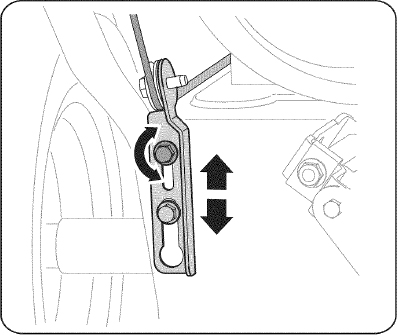
Figure 9
- Position the bracket upward to provide more slack (or downward to increase cable tension).
- Retighten the upper hex bolt.
- Repeat steps 2-6 above to verify proper adjustment has been achieved.
OPERATION
Now that you have set up your snow thrower, it’s important to become acquainted with its controls and features. Refer to Figure 10.
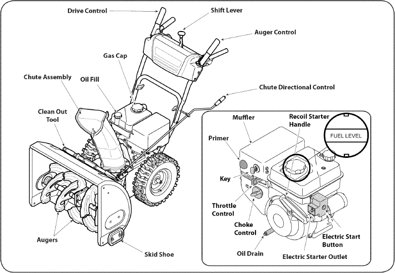
Figure 10
SHIFT LEVER

The shift lever is located on the dash panel. Place the shift lever into any of eight positions to control the direction of travel and ground speed.
Forward
Your snow thrower has six forward (F) speeds. Position one (1) is the slowest and position six (6) is the fastest.
Reverse
Your snow thrower has two reverse (R) speeds. One (1) is the slower and two (2) is the faster.
KEY
The key is a safety device. It must be fully inserted in order for the engine to start. Remove the key when the snow thrower is not in use.

NOTE: Do not turn the ignition key in an attempt to start the engine. Doing so may cause it to break.

CHOKE CONTROL
The choke control is found on the rear of the engine and is activated by turning the rotary choke knob to the CHOKE position. Activating the choke control closes the choke plate on the carburetor and aids in starting the engine.

Meets ANSI Safety Standards
Craftsman Snow Throwers conform to the safety standard of the American National Standards Institute (ANSI).
THROTTLE CONTROL
The throttle control is located on the rear of the engine. It regulates the speed of the engine and will shut off the engine when moved into the OFF position.
PRIMER
Depressing the primer forces fuel directly into the engine’s carburetor to aid in cold-weather starting.
RECOIL STARTER HANDLE
This handle is used to manually start the engine.
ELECTRIC STARTER BUTTON
Pressing the electric starter button engages the engine’s electric starter when plugged into a 120V power source.
ELECTRIC STARTER OUTLET
Requires the use of a three-prong outdoor extension cord (included) and a 120V power source/wall outlet.
OIL FILL
Engine oil level can be checked and oil added through the oil fill.
GAS CAP
Unthread the gas cap to add gasoline to the fuel tank.
AUGER
When engaged, the auger blades rotate and draw snow into the auger housing.
CHUTE ASSEMBLY
Snow drawn into the auger housing is discharged out the chute assembly.
AUGER CONTROL
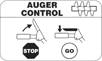
The auger control is located on the left handle. Squeeze the control grip against the handle to engage the auger and start snow throwing action. Release to stop.
DRIVE CONTROL/ AUGER CONTROL LOCK
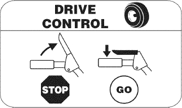
The drive control is located on the right handle. Squeeze the control grip against the handle to engage the wheel drive. Release to stop. The drive control also locks the auger control so you can operate the chute directional control without interrupting the snow throwing process. If the auger control is engaged simultaneously with the drive control, the operator can release the auger control (on the left handle) and the augers will remain engaged. Release both controls to stop the augers and wheel drive.
NOTE: Always release the drive control before changing speeds. Failure to do so will result in increased wear on your machine’s drive system.
CHUTE DIRECTIONAL CONTROL
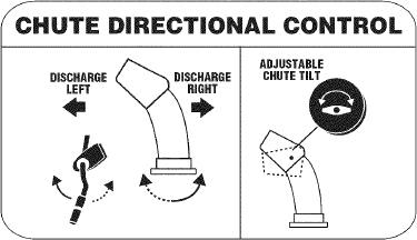
The chute directional control is located on left side of the snow thrower. To change the direction in which snow is thrown, rotate the chute directional control.
SKID SHOES
Position the skid shoes based on surface conditions. Adjust upward for hard-packed snow. Adjust downward when operating on gravel or crushed rock surfaces.
CLEAN-OUT TOOL
WARNINGNever use your hands to clear a clogged chute assembly. Shut off engine and remain behind handles until all moving parts have stopped before using the clean-out tool to clear the chute assembly.
The chute clean-out tool is conveniently fastened to the rear of the auger housing with a mounting clip. Should snow and ice become lodged in the chute assembly during operation, proceed as follows to safely clean the chute assembly and chute opening:
- Release both the Auger Control and the Drive Control.
- Stop the engine by removing the ignition key.
- Remove the clean-out tool from the clip which secures it to the rear of the auger housing.
- Use the shovel-shaped end of the clean-out tool to dislodge and scoop any snow and ice which has formed in and near the chute assembly.
- Refasten the clean-out tool to the mounting clip on the rear of the auger housing, reinsert the ignition key and start the snow thrower’s engine.
- While standing in the operator’s position (behind the snow thrower), engage the auger control for a few seconds to clear any remaining snow and ice from the chute assembly.
BEFORE STARTING ENGINE
WARNINGRead, understand, and follow all instructions and warnings on the machine and in this manual before operating.
Oil
The unit was shipped with oil in the engine. Check oil level before each operation to ensure adequate oil in the engine. For further instructions, refer to the steps on page 16.
NOTE: Be sure to check the engine on a level surface with the engine stopped.
- Remove the oil filler cap/dipstick and wipe the dipstick clean.
- Insert the cap/dipstick into the oil filler neck, but do NOT screw it in.
- Remove the oil filler cap/dipstick. If the level is low, slowly add oil (5W-30, with a minimum classification of SF/SG) until oil level registers between high (H) and low (L).
NOTE: Do not overfill. Overfilling with oil may result in engine smoking, hard starting or spark plug fouling.
- Replace and tighten cap/dipstick firmly before starting engine.
Gasoline
Use automotive gasoline (unleaded or low leaded to minimize combustion chamber deposits) with a minimum of 87 octane. Gasoline with up to 10% ethanol or 15% MTBE (Methyl Tertiary Butyl Ether) can be used. Never use an oil/gasoline mixture or dirty gasoline. Avoid getting dirt, dust, or water in the fuel tank. DO NOT use E85 gasoline.
- Refuel in a well-ventilated area with the engine stopped. Do not smoke or allow flames or sparks in the area where the engine is refueled or where gasoline is stored.
- Do not overfill the fuel tank. After refueling, make sure the tank cap is closed properly and securely.
- Be careful not to spill fuel when refueling. Spilled fuel or fuel vapor may ignite. If any fuel is spilled, make sure the area is dry before starting the engine.
- Avoid repeated or prolonged contact with skin or breathing of vapor.
WARNINGUse extreme care when handling gasoline. Gasoline is extremely flammable and the vapors are explosive. Never fuel the machine indoors or while the engine is hot or running. Extinguish cigarettes, cigars, pipes and other sources of ignition.
- Clean around fuel fill before removing cap to fuel.
- A fuel level indicator is located in the fuel tank. See Figure 10 inset. Be careful not to overfill. Fill tank until fuel reaches the fuel level indicator to allow space for fuel expansion.
STARTING THE ENGINE
WARNINGAlways keep hands and feet clear of moving parts. Do not use a pressurized starting fluid. Vapors are flammable.
NOTE: Allow the engine to warm up for a few minutes after starting. The engine will not develop full power until it reaches operating temperatures.
- Make certain both the auger control and drive control are in the disengaged (released) position.
- Insert key into slot. Make sure it snaps into place. Do not attempt to turn the key.
NOTE: The engine cannot start without the key fully inserted into the ignition switch.
Electric Starter
WARNINGThe optional electric starter is equipped with a grounded three-wire power cord and plug, and is designed to operate on 120 volt AC household current. It must be used with a properly grounded three- prong receptacle at all times to avoid the possibility of electric shock. Follow all instructions carefully prior to operating the electric starter. DO NOT use electric starter in the rain.
Determine that your home’s wiring is a three-wire grounded system. Ask a licensed electrician if you are not certain.
If you have a grounded three-prong receptacle, proceed as follows.
If you do not have the proper house wiring, DO NOT use the electric starter under any conditions.
- Plug the extension cord into the outlet located on the engine’s surface. Plug the other end of extension cord into a three-prong 120-volt, grounded, AC outlet in a well-ventilated area.
- Move throttle control to FAST (rabbit)
 position.
 - Move choke to the CHOKE
 position (cold engine start). If engine is warm, place choke in RUN position.
 - Push primer three (3) times, making sure to cover vent hole in primer bulb when pushing. If engine is warm, push primer only once. Always cover vent hole when pushing. Cool weather may require priming to be repeated.
- Push starter button to start engine. Once the engine starts, immediately release starter button. Electric starter is equipped with thermal overload protection; system will temporarily shut-down to allow starter to cool if electric starter becomes overloaded.
- As the engine warms, slowly rotate the choke control to RUN position. If the engine falters, restart engine and run with choke at half-choke position for a short period of time, and then slowly rotate the choke into RUN position.
- After engine is running, disconnect power cord from electric starter. When disconnecting, always unplug the end at the wall outlet before unplugging the opposite end from the engine.
Recoil Starter
CAUTIONDo not pull the starter handle while the engine running.
- Move throttle control to FAST (rabbit) position.
- Move choke to the CHOKE position (cold engine start). If engine is warm, place choke in RUN position.
- Push primer three (3) times, making sure to cover vent hole when pushing. If engine is warm, push primer only once. Always cover vent hole when pushing. Cool weather may require priming to be repeated.
- Pull gently on the starter handle until it begins to resist, then pull quickly and forcefully to overcome the compression. Do not release the handle and allow it to snap back. Return rope SLOWLY to original position. If required, repeat this step.
- As the engine warms, slowly rotate the choke control to RUN position. If the engine falters, restart engine and run with choke at half-choke position for a short period of time, and then slowly rotate the choke into RUN position.
WARNINGTo avoid unsupervised engine operation, never leave the machine unattended with the engine running. Turn the engine off after use and remove key.
STOPPING THE ENGINE
After you have finished snow-throwing, run engine for a few minutes before stopping to help dry off any moisture on the engine.
- Move throttle control to OFF position.
- Remove the key. Removing the key will reduce the possibility of unauthorized starting of the engine while equipment is not in use. Keep the key in a safe place. The engine cannot start without the key.
- Wipe any moisture away from the controls on the engine.
TO ENGAGE DRIVE
- With the throttle control in the Fast (rabbit) position, move shift lever into one of the six forward (F) positions or two reverse (R) positions. Select a speed appropriate for the snow conditions and a pace you’re comfortable with.
NOTE: When selecting a Drive Speed, use the slower speeds until you are comfortable and familiar with the operation of the snow thrower.
- Squeeze the drive control against the handle and the snow thrower will move. Release it and drive motion will stop.
NOTE: NEVER reposition the shift lever (change speeds or direction of travel) without first releasing the drive control and bringing the snow thrower to a complete stop. Doing so will result in premature wear to the snow thrower’s drive system.
TO ENGAGE AUGER
- To engage the auger and start throwing snow, squeeze the auger control against the left handle. Release to stop the auger.
REPLACING SHEAR PINS
Each auger blade is secured to the spiral shaft with a shear pin and bow-tie clip. If an auger blade strikes a foreign object or ice jam, the pin will shear off to prevent damage to the blade. If an auger blade does not turn, check to see if its pin has sheared off. See Figure 11.
Figure 11
CAUTIONNEVER replace the auger shear pins with anything other than Sears SKU# 88389/OEM Part No. 738-04124A replacement shear pins. Any damage to the auger gearbox or other components as a result of failing to do so will NOT be covered by your snow thrower’s warranty.
WARNINGAlways turn off the snow thrower’s engine and remove the key prior to replacing shear pins.
SERVICE AND MAINTENANCE
MAINTENANCE SCHEDULE
WARNINGBefore performing any type of maintenance/service, disengage all controls and stop the engine. Wait until all moving parts have come to a complete stop. Disconnect spark plug wire and ground it against the engine to prevent unintended starting. Always wear safety glasses during operation or while performing any adjustments or repairs.
Follow the maintenance schedule given below. This chart describes service guidelines only. Use the Service Log column to keep track of completed maintenance tasks. To locate the nearest Sears Service Center or to schedule service, simply contact Sears at 1-800-4-MY-HOME®.
| Interval | Item | Service | Service Log |
|---|---|---|---|
| Each Use and every 5 hours | 1. Engine oil level 2. Loose or missing hardware 3. Unit and engine. |
1. Check 2. Tighten or replace 3. Clean |
|
| 1st 5 hours | 1. Engine oil | 1. Change | |
| Annually or 25 hours | 1. Spark plug 2. Control linkages and pivots 3. Wheels 4. Gear shaft and Auger shaft |
1. Check 2. Lube with light oil 3. Lube with multipurpose auto grease 4. Lube with light oil |
|
| Annually or 50 hours | 1. Engine oil | 1. Change | |
| Annually or 100 hours | 1. Spark plug | 1. Change | |
| Before Storage | 1. Fuel system | 1. Run engine until it stops from lack of fuel |
ENGINE MAINTENANCE
Checking Engine Oil
WARNINGBefore lubricating, repairing, or inspecting, disengage all controls and stop engine. Wait until all moving parts have come to a complete stop.
NOTE: Check the oil level before each use to be sure correct oil level is maintained.
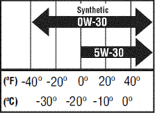
When adding oil to the engine, refer to viscosity chart below. Engine oil capacity is 600 ml (approx. 20 oz.). Do not over-fill. Use a 4-stroke, or an equivalent high detergent, premium quality motor oil certified to meet or exceed U.S. automobile manufacturer's requirements for service classification SG, SF. Motor oils classified SG, SF will show this designation on the container.
- Remove the oil filler cap/dipstick and wipe the dipstick clean.
- Insert the cap/dipstick into the oil filler neck, but do NOT screw it in.
- Remove the oil filler cap/dipstick. If level is low, slowly add oil until oil level registers between high (H) and low (L). See Figure 12.
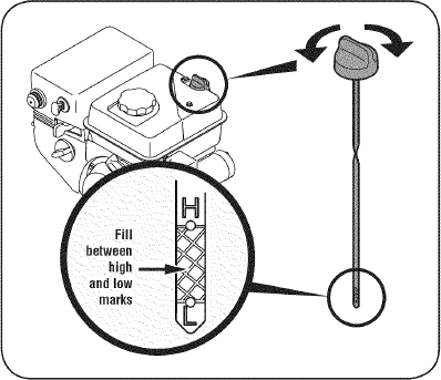
Figure 12
- Replace and tighten cap/dipstick firmly before starting engine.
Changing Engine Oil
NOTE: Change the engine oil after the first 5 hours of operation and once a season or every 50 hours thereafter.
- Drain fuel from tank by running engine until the fuel tank is empty. Be sure fuel fill cap is secure.
- Place suitable oil collection container under oil drain plug.
- Remove oil drain plug. See Figure 13 on next page.
- Tip engine to drain oil into the container. Used oil must be disposed of at a proper collection center.
CAUTIONUsed oil is a hazardous waste product. Dispose of used oil properly. Do not discard with household waste. Check with your local authorities or Sears Service Center for safe disposal/recycling facilities.
- Reinstall the drain plug and tighten it securely.
- Refill with the recommended oil and check the oil level. See Recommended Oil Usage chart. The engine's oil capacity is 20 ounces.
CAUTIONDO NOT use nondetergent oil or 2-stroke engine oil. It could shorten the engine's service life.
- Reinstall the oil filler cap/dipstick securely.
CAUTIONThoroughly wash your hands with soap and water as soon as possible after handling used oil.
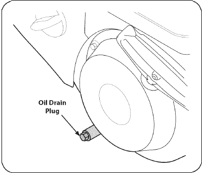
Figure 13
Checking Spark Plug
WARNINGDO NOT check for spark with spark plug removed. DO NOT crank engine with spark plug removed.
WARNINGIf the engine has been running, the muffler will be very hot. Be careful not to touch the muffler.
NOTE: Check the spark plug once a season or every 25 hours of operation. Change the spark plug once a season or every 100 hours. To ensure proper engine operation, the spark plug must be properly gapped and free of deposits.
- Remove the spark plug boot and use a spark plug wrench to remove the plug. See Figure 14.
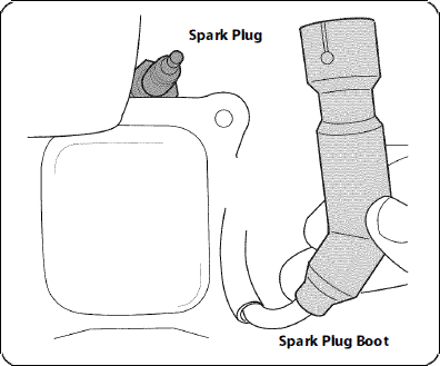
Figure 14
- Visually inspect the spark plug. Discard the spark plug if there is apparent wear, or if the insulator is cracked or chipped. Clean the spark plug with a wire brush if it is to be reused.
- Measure the plug gap with a feeler gauge. Correct as necessary by bending side electrode. See Figure 15. The gap should be set to .02-.03 inches (0.60-0.80 mm).
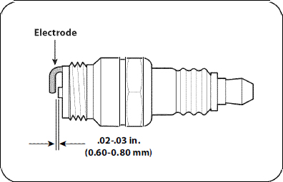
Figure 15
- Check that the spark plug washer is in good condition and thread the spark plug in by hand to prevent cross-threading.
- After the spark plug is seated, tighten with a spark plug wrench to compress the washer.
NOTE: When installing a new spark plug, tighten 1/2-tum after the spark plug seats to compress the washer. When reinstalling a used spark plug, tighten 1/8- to 1/4-turn after the spark plug seats to compress the washer.
CAUTIONThe spark plug must be tightened securely. A loose spark plug can become very hot and can damage the engine.
LUBRICATION
Gear Shaft
The gear (hex) shaft should be lubricated at least once a season or after every 25 hours of operation.
- To prevent spillage, remove all fuel from tank by running engine until it stops.
- Carefully pivot the snow thrower up and forward so that it rests on the auger housing.
- Remove the lower frame cover from the underside of the snow thrower by removing the self-tapping screws which secure it.
- Apply a light coating of engine oil (or 3-in-1 oil) to the hex shaft. See Figure 16.
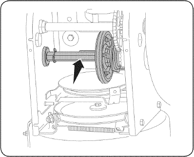
Figure 16
NOTE: When lubricating the hex shaft, be careful not to get any oil on the aluminum drive plate or rubber friction wheel. Doing so will hinder the snow thrower's drive system. Wipe off any excess or spilled oil.
Wheels
At least once a season, remove both wheels. Clean and coat the axles with a multipurpose automotive grease before reinstalling wheels.
Chute Directional Control
Once a season, lubricate the eye bolt bushing and the spiral with 3-in-1 oil.
Auger Shaft
At least once a season, remove the shear pins on auger shaft. Spray lubricant inside shaft, and around the spacers and flange bearings found at either end of the shaft. See Figure 17.
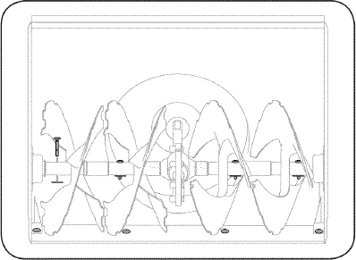
Figure 17
SHAVE PLATE AND SKID SHOES
The shave plate and skid shoes on the bottom of the snow thrower are subject to wear. They should be checked periodically and replaced when necessary.
NOTE: The skid shoes on this machine have two wear edges. When one side wears out, they can be rotated 180° to use the other edge.
To remove skid shoes:
- Remove the two carriage bolts, washers, and hex flange nuts that secure each skid shoe to the snow thrower.
- Reassemble new skid shoes with the four carriage bolts (two on each side), washers, and hex flange nuts. Refer to Figure 18.
To remove shave plate:
- Remove the carriage bolts and hex nuts which attach it to the snow thrower housing.
- Reassemble new shave plate, making sure heads of carriage bolts are to the inside of housing. Tighten securely. See Figure 18.
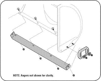
Figure 18
ADJUSTMENTS
Shift Cable
If the full range of speeds (forward and reverse) cannot be achieved, refer to the figure to the right and adjust the shift cable as follows:
- Place the shift lever in the fastest forward speed position (F6).
- Loosen the hex nut on the shift cable index bracket. See Figure 19
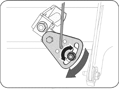
Figure 19
- Pivot the bracket downward to take up slack in the cable.
- Retighten the hex nut.
Drive Control
When the drive control is released and in the disengaged “up” position, the cable should have very little slack. It should NOT be tight. Also, if there is excessive slack in the drive cable or if the unit experiences intermittent drive while using, the cable may need to be adjusted.
Check the adjustment of the drive control as follows:
- With the drive control released, push the snow thrower gently forward. The unit should roll freely.
- Engage the drive control and gently attempt to push the snow thrower forward. The wheels should not turn. The unit should not roll freely.
- With the drive control released, move the shift lever back and forth between the R2 position and the F6 position several times. There should be no resistance in the shift lever.
- If any of the above tests failed, the drive cable is in need of adjustment. Proceed as follows:
- Shut off the engine as instructed in the Operation section.
- Loosen the lower hex bolt on the drive cable bracket. See Figure 20.
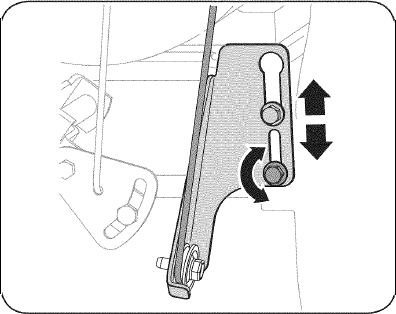
Figure 20
- Position the bracket upward to provide more slack (or downward to increase cable tension).
- Retighten the lower hex bolt.
Chute Bracket
If the spiral at the bottom of the chute directional control is not fully engaging with the chute assembly, the chute bracket can be adjusted. To do so:
- Loosen the two nuts which secure the chute bracket and reposition it slightly. See Figure 21.
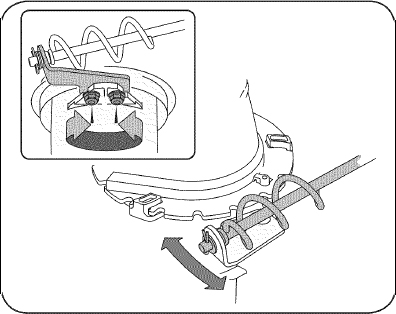
Figure 21
- Retighten the nuts.
Auger Control
Refer to the Assembly section for instructions on adjusting the auger control cable.
Skid Shoes
Refer to the Assembly section for instructions on adjusting the skid shoes.
BELT REPLACEMENT
Auger Belt
To remove and replace your snow thrower's auger belt, proceed as follows:
- To prevent spillage, remove all fuel from tank by running engine until it stops.
- Remove the plastic belt cover on the front of the engine by removing the two self-tapping screws. See Figure 22.
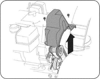
Figure 22
- Roll the auger belt off the engine pulley. See Figure 23.
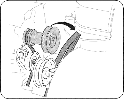
Figure 23
- Carefully pivot the snow thrower up and forward so that it rests on the auger housing.
- Remove the frame cover from the underside of the snow thrower by removing four self-tapping screws which secure it. See Figure 24
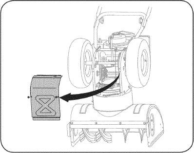
Figure 24
- Remove the belt as follows. Refer to Figure 25.
- Loosen and remove the shoulder screw which acts as a belt keeper.
- Unhook the auger brake bracket spring from the frame.

Figure 25
- Remove the belt from around the auger pulley, and slip the belt between the support bracket and the auger pulley. See Figure 26.
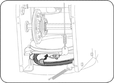
Figure 26
- Reassemble auger belt by following instructions in reverse order.
- Perform the Auger Control test outlined in the Assembly section of this manual.
NOTE: Do NOT forget to reinstall the shoulder screw and reconnect the spring to the frame after installing a replacement auger belt.
Drive Belt
To remove and replace your snow thrower's drive belt, proceed as follows:
- To prevent spillage, remove all fuel from tank by running engine until it stops.
- Remove the plastic belt cover on the front of the engine by removing the two self-tapping screws. See Figure 22 on previous page.
- Remove the belt as follows. Refer to Figure 27.
- Roll the auger belt off the engine pulley.
- Use a wrench to pivot the idler pulley toward the right.
- Lift the drive belt off engine pulley.
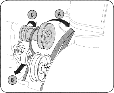
Figure 27
- Carefully pivot the snow thrower up and forward so that it rests on the auger housing.
- Remove the frame cover from the underside of the snow thrower by removing the self-tapping screws which secure it. Refer to Figure 24.
- Back out the stop bolt to increase the clearance between the friction wheel disc and friction wheel. See Figure 28.
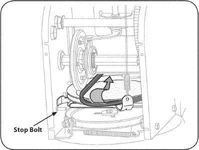
Figure 28
- Slip the drive belt off the pulley and between friction wheel and friction wheel disc. See Figure 28.
- Remove and replace belt in the reverse order. Be sure to reinstall the stop bolt.
FRICTION WHEEL REMOVAL
If the snow thrower fails to drive with the drive control engaged, and performing the drive control cable adjustment fails to correct the problem, the friction wheel may need to be replaced. Follow the instructions below. Examine the friction wheel for signs of wear or cracking and replace if necessary.
- To prevent spillage, remove all fuel from tank by running engine until it stops.
- Place the shift lever in third Forward (F3) position.
- Carefully pivot the snow thrower up and forward so that it rests on the auger housing.
- Remove the frame cover from the underside of the snow thrower by removing the self-tapping screws which secure it.
- Remove the right-hand wheel by removing the screw and bell washer which secure it to the axle. See Figure 29.

Figure 29
- Carefully remove the hex nut and washer which secures the hex shaft to the snow thrower frame and lightly tap the shaft's end to dislodge the ball bearing from the right side of the frame. See Figure 30.
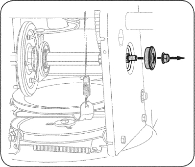
Figure 30
NOTE: Be careful not to damage the threads on the shaft.
- Carefully position the hex shaft downward and to the left before carefully sliding the friction wheel assembly off the shaft. See Figure 31.
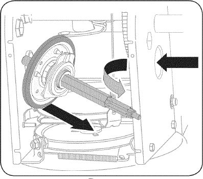
Figure 31
NOTE: If you're replacing the friction wheel assembly as a whole, discard the worn part and slide the new part onto the hex shaft.
- Follow the steps above in reverse order to reassemble components.
- Perform the test previously described in the Drive Control section.
If you're disassembling the friction wheel and replacing only the rubber ring, proceed as follows:
- Remove the four screws which secure the friction wheel's side plates together. See Figure 32.
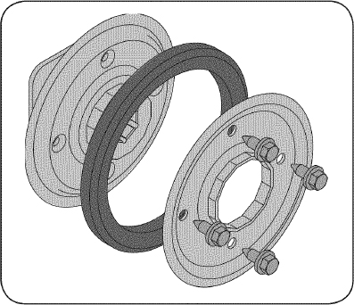
Figure 32
- Remove the rubber ring from between the plates.
- Reassemble the side plates with a new rubber ring.
NOTE: When reassembling the friction wheel assembly, make sure that the rubber ring is centered and seated properly between the side plates. Tighten each screw only one rotation before turning the wheel clockwise and proceeding with the next screw. Repeat this process several times to ensure the plates are secured with equal force (between 6 ft-lbs and 9 ft-lbs).
- Slide the friction wheel assembly back onto the hex shaft and follow the steps above in reverse order to reassemble components.
- Perform the test previously described in the Drive Control section.
OFF-SEASON STORAGE
If the snow thrower will not be used for 30 days or longer, or if it is the end of the snow season when the last possibility of snow is gone, the equipment needs to be stored properly. Follow storage instructions below to ensure top performance from the snow thrower for many more years.
PREPARING ENGINE
Engines stored over 30 days need to be drained of fuel to prevent deterioration and gum from forming in fuel system or on essential carburetor parts. If the gasoline in your engine deteriorates during storage, you may need to have the carburetor, and other fuel system components, serviced or replaced.
- Remove all fuel from tank by running engine until it stops. Do not attempt to pour fuel from the engine.
- Change the engine oil.
- Remove spark plug and pour approximately 1 oz. (30 ml) of clean engine oil into the cylinder. Pull the recoil starter several times to distribute the oil, and reinstall the spark plug.
- Clean debris from around engine, and under, around, and behind muffler. Apply a light film of oil on any areas that are susceptible to rust.
- Store in a clean, dry and well ventilated area away from any appliance that operates with a flame or pilot light, such as a furnace, water heater, or clothes dryer. Avoid any area with a spark producing electric motor, or where power tools are operated.
WARNINGNever store snow thrower with fuel in tank indoors or in poorly ventilated areas, where fuel fumes may reach an open flame, spark or pilot light as on a furnace, water heater, clothes dryer or gas appliance.
- If possible, avoid storage areas with high humidity.
- Keep the engine level in storage. Tilting can cause fuel or oil leakage.
PREPARING SNOW THROWER
- When storing the snow thrower in an unventilated or metal storage shed, care should be taken to rustproof the equipment. Using a light oil or silicone, coat the equipment, especially any chains, springs, bearings and cables.
- Remove all dirt from exterior of engine and equipment.
- Follow lubrication recommendations.
- Store equipment in a clean, dry area.
TROUBLESHOOTING
| Problem | Cause | Remedy |
|---|---|---|
| Engine fails to start | 1. Choke control not in CHOKE position. 2. Spark plug wire disconnected. 3. Faulty spark plug. 4. Fuel tank empty or stale fuel. 5. Engine not primed. 6. Key not inserted. 7. Extension cord not connected (when using electric start button, on models so equipped). |
1. Move choke control to CHOKE position. 2. Connect wire to spark plug. 3. Clean, adjust gap, or replace. 4. Fill tank with clean, fresh gasoline. 5. Prime engine as instructed in the Operation Section. 6. Insert key fully into the switch. 7. Connect one end of the extension cord to the electric starter outlet and the other end to a three-prong 120-volt, grounded, AC outlet. |
| Engine running erratically/inconsistent RPM (hunting or surging) | 1. Engine running on CHOKE. 2. Stale fuel. 3. Water or dirt in fuel system. 4. Over-governed engine. |
1. Move choke control to RUN position. 2. Fill tank with clean, fresh gasoline. 3. Drain fuel tank by running engine until it stops. Refill with fresh fuel. 4. Contact your Sears Parts & Repair Center. |
| Excessive vibration | 1. Loose parts or damaged auger. | 1. Stop engine immediately and disconnect spark plug wire. Tighten all bolts and nuts. If vibration continues, have unit serviced by a Sears Parts & Repair Center. |
| Loss of power | 1. Spark plug wire loose. 2. Gas cap vent hole plugged. |
1. Connect and tighten spark plug wire. 2. Remove ice and snow from gas cap. Be certain vent hole is clear. |
| Unit fails to propel itself | 1. Drive cable in need of adjustment. 2. Drive belt loose or damaged. 3. Worn friction wheel. |
1. Adjust drive control cable. Refer to Service and Maintenance section. 2. Replace drive belt. Refer to Service and Maintenance section. 3. Change friction wheel or contact your Sears Parts & Repair Center. |
| Unit fails to discharge snow | 1. Chute assembly clogged. 2. Foreign object lodged in auger. 3. Auger cable in need of adjustment. 4. Auger belt loose or damaged. 5. Shear pin(s) sheared. |
1. Stop engine immediately and disconnect spark plug wire. Clean chute assembly and inside of auger housing with clean-out tool or a stick. 2. Stop engine immediately and disconnect spark plug wire. Remove object from auger with clean-out tool or a stick. 3. Adjust auger control cable. Refer to Assembly section. 4. Replace auger belt. Refer to Service and Maintenance section. 5. Replace with new shear pin(s). |
| Chute fails to easily rotate 180 degrees | 1. Chute assembled incorrectly. | 1. Disassemble chute control and reassemble as directed in the Assembly section. |
NEED MORE HELP?
You'll find the answer and more on managemylife.com ‒ for free!
- Find this and all your other product manuals online.
- Get answers from our team of home experts.
- Get a personalized maintenance plan for your home.
- Find information and tools to help with home projects.

brought to you by Sears
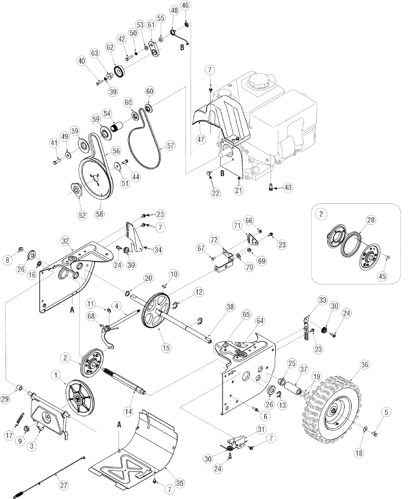
PARTS LIST
Craftsman Snow Thrower Model 247.889571
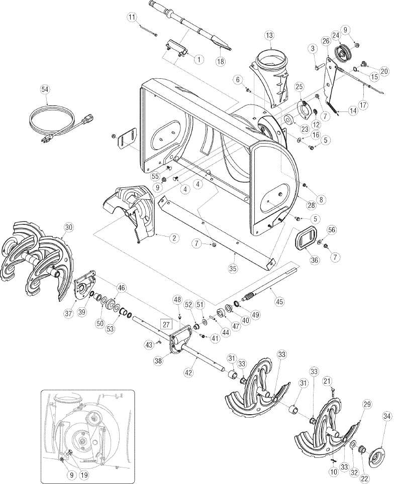
| Ref. No. | Part No. | Description |
|---|---|---|
| 1. | 731-2635 | Snow Removal Tool Mount |
| 2. | 684-04057A-0637 | Impeller Assembly, 12” Dia. |
| 3. | 710-0347 | Hex Screw, 3/8-16, 1.75, Gr5 |
| 4. | 710-0451 | Bolt, Carriage, 5/16-18, .750 Gr1 |
| 5. | 710-04484 | Screw, 5/16-18, 0.750 |
| 6. | 710-0703 | Screw, Carriage, 1/4-20, .750, Gr5 |
| 7. | 712-04063 | Nut, Flange Lock, 5/16-18, Nylon |
| 8. | 712-04064 | Nut, Flange Lock, 1/4-20, Nylon |
| 9. | 712-04065 | Nut, Flange Lock, 3/8-16, Nylon |
| 10. | 714-04040 | Cotter Pin, Bow-tie |
| 11. | 725-0157 | Cable, Tie, 3/16 × .05 × 7.4 |
| 12. | 926-04012 | Nut, Push-on, .25 Dia |
| 13. | 731-04705D | Chute, Adapter 5” Dia |
| 14. | 732-04460 | Spring, Extension, .38 OD × 4.59 |
| 15. | 736-0174 | Washer, Wave, .625 × .885 × .015 |
| 16. | 736-0242 | Washer, Bell, .340 × .872 × .060 |
| 17. | 746-04230 | Clutch Cable, Auger, 47.23” |
| 18. | 931-2643 | Snow Removal Tool |
| 19. | 738-0143 | Screw, Shoulder, .498 × .34, 3/8-16 |
| 20. | 938-0281 | Screw, Shoulder, .625 × .17, 3/8-16 |
| 21. | 738-04124A | Shear Pin, .25 × 1.50 |
| 22. | 941-0245 | Bearing, Hex Flange × .75 ID |
| 23. | 941-0309 | Bearing, Ball, .75 ID × 1.85 OD |
| 24. | 756-04224 | Flat Pulley, Idler, 2.75 OD |
| 25. | 790-00075 | Housing, Bearing, 1.85 ID |
| 26. | 790-00080A-0637 | Bracket, Auger Idler w/ Brake |
| 27. | 918-04171B | Gearbox Assembly, Auger, 24” |
| 28. | 684-04265-4044 | Housing Assembly, Auger 24” |
| 29. | 684-04107-0637 | Spiral Assembly, LH |
| 30. | 684-04108-0637 | Spiral Assembly, RH |
| 31. | 731-04870 | Spacer, 1.25 OD × .75 ID × 1.00 |
| 32. | 736-0188 | Washer, Flat, .76 × 1.49 × .06 |
| 33. | 741-0493A | Bushing, Flange, .80 ID × .91 OD |
| 34. | 790-00087A-0637 | Housing, 1” Hex Bearing |
| 35. | 790-00120-4044 | Shave Plate, 2.25 × 23.66 |
| 36. | 731-06439 | Slide Shoe |
| 37. | 918-0123A | Housing, Auger, RH |
| 38. | 918-0124A | Housing, Auger, LH |
| 39. | 921-0338 | Seal, Oil, .750x 1.00x.125 |
| 40. | 741-0662 | Bearing, Flange, .75 × 1.0 × .59 |
| 41. | 710-0642 | Screw, Self-tapping, 1/4-20, 0.750 |
| 42. | 711-04285 | Axle, Auger, 24” |
| 43. | 914-0161 | Key, Hi-pro 3/16 × 5/8 |
| 44. | 715-04021 | Pin, Dowel, .25 OD × 1.2 |
| 45. | 917-04126 | Shaft, Worm .75 OD |
| 46. | 917-04861 | Gear, Worm 20T |
| 47. | 718-04071 | Collar, Thrust |
| 48. | 721-0325 | Plug, 1/4 × .437 |
| 49. | 721-0327 | Seal, Oil, .75 × 1 × .131 |
| 50. | 936-0351 | Washer, Flat, .760 ID × 1.5 OD |
| 51. | 736-3084 | Washer, Flat, .51 × 1.12 |
| 52. | 741-0663 | Bearing, Flange, .75 × 1.0 × .925 |
| 53. | 741-0661A | Bearing, Flange, .75 × 1.00 × .975 |
| 54. | 929-0071A | Extension Cord, 110V |
| 55. | 710-0276 | Screw, Carriage, 5/16-18 × 1.00 |
| 56. | 936-0159 | Washer, Flat, .349 × .879 × .063 |
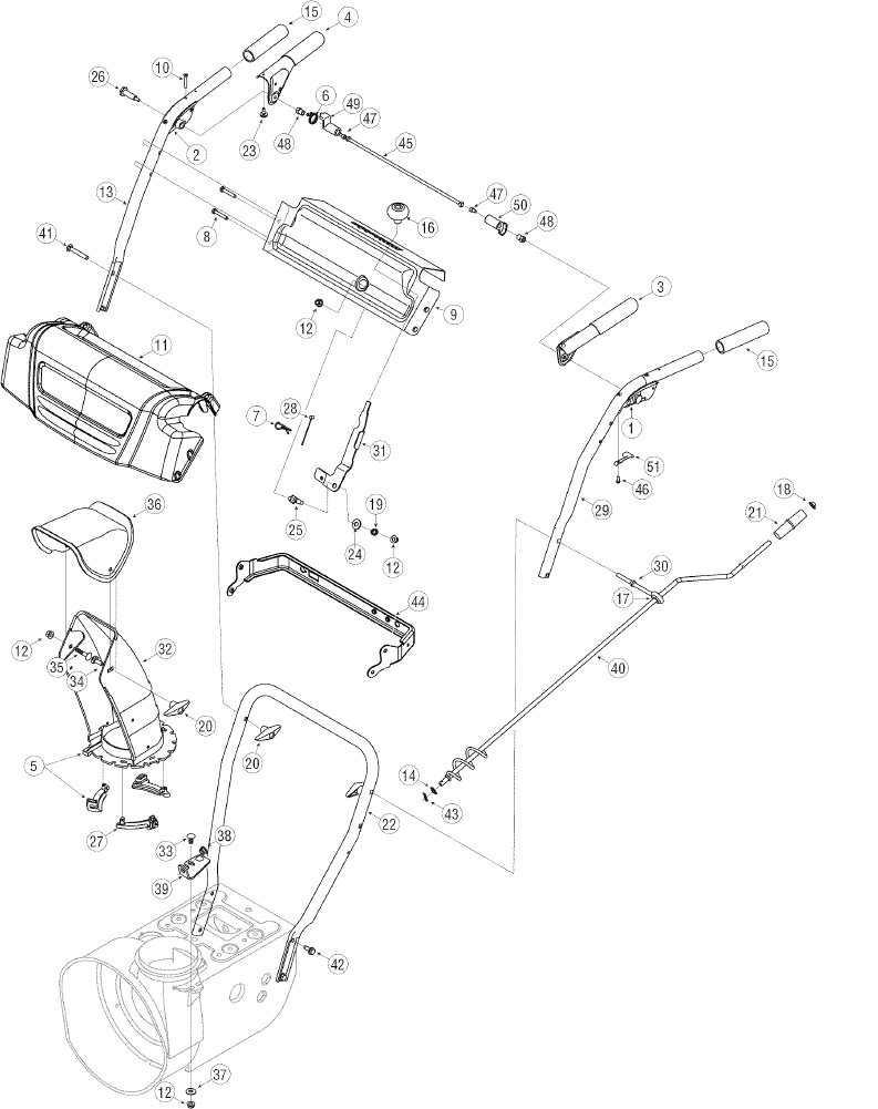
| Ref. No. | Part No. | Description |
|---|---|---|
| 1. | 631-04133A | Handle Assembly, Clutch Lock, LH |
| 2. | 631-04134B | Handle Assembly, Clutch Lock, RH |
| 3. | 684-04111B | Handle Ass’y, Engage, Red, LH |
| 4. | 684-04112B | Handle Ass’y, Engage, Red, RH |
| 5. | 631-04131B | Chute, Lower (Incl. Ref. # 27, Qty. 3) |
| 6. | 732-04238 | Spring, Torsion, .8156 ID × .3038 |
| 7. | 914-0145 | Click Pin |
| 8. | 710-04586 | Screw, 1/4-20 × 1.625 |
| 9. | 790-00219-4044 | Panel, Handle, (no cutout) |
| 10. | 710-1233 | Screw, Machine, #10-24, 1.375 |
| 11. | 731-06471 | Handle Panel Cover |
| 12. | 712-04063 | Nut, Flange Lock, 5/16-18, Nylon |
| 13. | 749-04190A-0637 | Handle, Upper, RH |
| 14. | 936-0185 | Washer, Flat, .375 × .738 × .063 |
| 15. | 720-0274 | Grip, 1.0 ID × 5.0 |
| 16. | 720-04039 | Knob, Shift, Black |
| 17. | 735-0234 | Grommet, .44 ID × .94 OD × .50 |
| 18. | 926-0100 | Cap, Push, 3/8 Rod |
| 19. | 732-0193 | Spring, .39 × .60 × .88 |
| 20. | 720-0284 | Knob, 5/16-18, Black |
| 21. | 720-0201A | Crank Knob, 1.0 Dia. × 3.2, Black |
| 22. | 749-04138A-0637 | Handle, Lower |
| 23. | 935-0199A | Bumper, Rubber, .62 OD × .22 |
| 24. | 736-0262 | Washer, Flat, .385 × .870 × .092 |
| 25. | 738-04118 | Bolt, Shoulder, 5/16-18x0.905 |
| 26. | 738-04348 | Screw, Shoulder, .43 × 1.3, 1/4-20 |
| 27. | 731-04869A | Chute, Flange Keeper |
| 28. | 946-04397A | Cable, Speed Selector |
| 29. | 749-04191A-0637 | Handle, Upper, LH |
| 30. | 747-04263 | Eye Bolt, Chute Crank |
| 31. | 790-00313-0637 | Shift Lever |
| 32. | 731-04912B | Chute, Lower, 5.0 Dia. |
| 33. | 710-0276 | Bolt, Carriage, 5/16-18, 1.0 |
| 34. | 710-04071 | Bolt, Carriage, 5/16-18, 1.0 |
| 35. | 710-0451 | Bolt, Carriage, 5/16-18, .750 |
| 36. | 731-04426A | Chute, Upper, w/ Label |
| 37. | 936-0159 | Washer, .349 × .879 × .063 |
| 38. | 941-0475 | Bushing, Plastic, .380 |
| 39. | 784-5647-0637 | Bracket, Chute Crank |
| 40. | 684-04104-0637 | Crank Assembly, Chute |
| 41. | 710-0449 | Screw, Carriage, 5/16-18, 2.25 |
| 42. | 710-04484 | Screw, 5/16-18, 2.25, Gr5 |
| 43. | 914-0104 | Pin, Cotter, .072 × 1.13 |
| 44. | 790-00248B-0637 | Bracket, Panel |
| 45. | 684-04250 | Rod, Pivot |
| 46. | 710-04326 | Screw, #8-16 × .50 |
| 47. | 710-3069 | Screw, 1/4-20 × .50 |
| 48. | 712-04081A | Nut, Hex, 1/4-20 |
| 49. | 731-04894D | Plate, Lock |
| 50. | 731-04896B | Cam, Clutch Lock |
| 51. | 732-04219C | Spring, Clutch Lock |
| Ref. No. | Part No. | Description |
|---|---|---|
| 1. | 656-04055 | Disc Assembly, Friction Wheel |
| 2. | 684-04153 | Friction Wheel Assembly, 5.5 OD |
| 3. | 684-04154B-0637 | Support Bracket, Friction Wheel |
| 4. | 684-04156A | Shift Assembly, Rod |
| 5. | 710-0627 | Hex Screw, 5/16-24, .750, Gr5 |
| 6. | 710-0788 | Screw, 1/4-20, 1.000 |
| 7. | 710-1652 | Screw, 1/4-20 × .625 |
| 8. | 712-04065 | Nut, Flange Lock, 3/8-16, Nylon |
| 9. | 712-0417A | Nut, Flange, 5/8-18 |
| 10. | 914-0126 | Key, Hi Pro, 3/16x3/4 Dia. |
| 11. | 916-0104 | E-ring, .500 Dia. |
| 12. | 716-0136 | E-ring, Retaining, .875 Dia. |
| 13. | 916-0231 | E-ring, .750 Dia. |
| 14. | 917-04209A | Hex Shaft, .8125, 7-Tooth |
| 15. | 917-04230 | Gear, 80-Tooth |
| 16. | 726-0221 | Speed Nut, .500 |
| 17. | 932-0264 | Extension Spring |
| 18. | 736-0242 | Washer, Bell, .340 × .872 × .060 |
| 19. | 936-0287 | Washer, Flat, .793 × 1.24 × .060 |
| 20. | 736-04161 | Washer, Flat, .75 × 1.00 × .060 |
| 21. | 790-00289A-0637 | Plate, Cover |
| 22. | 738-04439 | Shoulder Screw |
| 23. | 738-04184A | Screw, Shoulder, .37 × .105, 1/4-20 |
| 24. | 738-0924A | Screw, 1/4-28, .375 |
| 25. | 941-0245 | Bearing, Hex Flange × .75 ID |
| 26. | 941-0563 | Bearing, Ball, 17 × 40 × 12 |
| 27. | 746-04229 | Clutch Cable, Wheel, 44.95” |
| 28. | 935-04054 | Rubber, Friction Wheel, 5.5 OD |
| 29. | 748-0190 | Spacer, .508 ID × .75 OD × .68 |
| 30. | 756-0625 | Roller, Cable |
| 31. | 790-00096-0637 | Front Guide Bracket, Auger Cable |
| 32. | 790-00180A-4044 | Frame |
| 33. | 790-00206A-0637 | Guide Bracket, Auger Cable |
| 34. | 790-00207B | Guide Bracket, Drive Cable |
| 35. | 790-00316-0637 | Cover, Frame |
| 36. | 634-04167A-0911 | LH Wheel Assembly |
| 634-04168A-0911 | RH Wheel Assembly | |
| 37. | 731-04873 | Spacer, 1.25 × .75 × 3.0 |
| 38. | 938-04168 | Axle, .75 × 22” |
| 39. | 736-0329 | Washer, Lock, 1/4 |
| 40. | 710-0809 | Hex Screw, 1/4-20, 1.25, Gr5 |
| 41. | 710-0191 | Hex Screw, 3/8-24, 1.25, Gr8 |
| 42. | 710-0672 | Hex Screw, 5/16-24, 1.25, Gr5 |
| 43. | 710-0654A | Screw, Sems, 3/8-16, 1.00 |
| 44. | 710-1245B | Hex Screw, 5/16-24, .875, Gr8 |
| 45. | 710-0896 | Screw, 1/4-20 × .625 |
| 46. | 926-04012 | Nut, Push-on, .25 Dia. |
| 47. | 731-04792A | Cover, Belt |
| 48. | 732-04308A | Spring, Torsion, .850 ID × .354 |
| 49. | 736-0247 | Washer, Flat, .406 × 1.25 × .157 |
| 50. | 936-0119 | Washer, Lock .3125 |
| 51. | 736-0505 | Washer, Flat, .34 × 1.50 × .150 |
| 52. | 748-04053A | Pulley, Adapter, .75 Dia. |
| 53. | 748-04112B | Spacer, Shoulder, .317 × .50 × .102 |
| 54. | 750-04303 | Spacer, .875 ID × 1.185 OD |
| 55. | 750-04477A | Spacer, .340 × .750 × .360 |
| 56. | 954-04050 | Belt, Auger Drive |
| 57. | 954-04260 | Belt, Wheel Drive |
| 58. | 756-04109 | Pulley, Auger Drive, 8.1 × .5 |
| 59. | 756-04113 | Pulley, Half, V × 2.600 OD |
| 60. | 756-04252 | Pulley, Half, 3/8-V × 1.7160 OD |
| 61. | 790-00208C | Idler Bracket, Wheel Drive |
| 62. | 684-04169 | Idler Pulley Assembly |
| 63. | 750-04571 | Spacer, Shoulder, .26 × .79 × .538 |
| 64. | 735-04099 | Plug, 3/8 ID |
| 65. | 735-04100 | Plug, 1/2 ID |
| 66. | 712-04064 | Nut, Flange Lock, 1/4-20, Nylon |
| 67. | 710-0751 | Hex Screw, 1/4-20, .620, Gr5 |
| 68. | 732-04311A | Spring, Torsion, .750 ID × .968 |
| 69. | 712-04063 | Nut, Flange Lock, 5/16-18, Nylon |
| 70. | 936-3015 | Wash, Flat, .469 × .875 × .105 |
| 71. | 790-00217A-0637 | Pivot Bracket, Speed Selector |
| 72. | 790-00218A-0637 | Shift Bracket, Speed Selector |
Craftsman Engine Model 265-SU-11 For Snow Model 247.889571
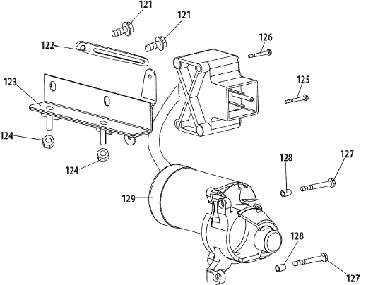
| Ref. | Part No. | Description |
|---|---|---|
| 121 | 710-04914 | Bolt M6×10 |
| 122 | 951-11680 | Wire Clip |
| 123 | 951-11114 | Switch Housing Mounting Bracket |
| 124 | 712-04212 | Nut M6 |
| 125 | 710-04965 | Bolt M4×55 |
| 126 | 710-04935 | Bolt M4×60 |
| 127 | 710-05182 | Bolt M6×32 |
| 128 | 715-04088 | Dowel Pin 8×8 |
| 129 | 951-10645A | Electric Starter |
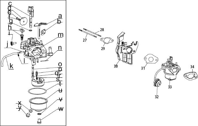
| Ret. | Part No. | Description |
|---|---|---|
| 27 | 710-04939 | Stud M6x117 |
| 28 | 710-04910 | Stud M6x105 |
| 29 | 951-11567 | Carburetor Insulator Gasket |
| 30 | 951-11896 | Carburetor Insulator |
| 31 | 951-11569A | Carburetor Gasket |
| 32 | 951-10639A | Primer Assembly |
| 32 | 951-11824 | Primer Bulb |
| 33 | 951-10974A | Carburetor Assembly |
| 34 | 951-11897 | Carburetor Gasket Plate |
| a | n/a | Choke Shaft |
| b | n/a | Choke Plate |
| c | n/a | Throttle Shaft |
| d | n/a | Throttle Plate |
| e | n/a | Screw M3x5 |
| f | n/a | Lock Washer |
| g | n/a | Gasket, Throttle Plate |
| h | n/a | Idle Jet Assembly |
| i | n/a | Idle Speed Adjusting Screw |
| j | n/a | Mixture Screw |
| k | 951-11699 | Primer Hose |
| I | 951-11906 | Hose Clamp |
| m | n/a | Carburetor Body |
| n | n/a | Float Pin |
| 0 | n/a | Emulsion Tube |
| P | n/a | Needle Valve |
| q | n/a | Main Jet |
| r | n/a | Needle Valve Spring |
| s | n/a | Float |
| t | 951-11589 | Fuel Bowl Gasket |
| u | n/a | Fuel Bowl |
| v | 951-11348 | Fuel Bowl Gasket |
| w | 710-04945 | Fuel Bowl Mounting Bolt |
| x | 951-11349 | Fuel Drain Plug Gasket |
| y | 710-04938 | Fuel Drain Plug |
| 951-11020A | Carburetor Kit - Major (lncl.g,h,l,n,o,p,q,r,s,t,v,x) |
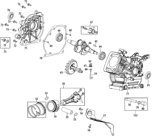
| Ref. | Part No. | Description |
|---|---|---|
| 52 | 951-11688 | Piston Ring Set |
| 53 | 951-11632 | Piston Pin Snap Ring |
| 54 | 951-11900 | Piston |
| 55 | 951-11901 | Piston Pin |
| 56 | 710-04915 | Bolt M6×12 |
| 57 | 951-11113 | Air Shield |
| 58 | 951-11573 | Connecting Rod Assembly |
| 59 | 951-11356 | Governor Arm Shaft |
| 60 | 736-04461 | Washer 5.2×1.9 |
| 61 | 951-11902 | Governor Seal |
| 62 | 714-04074 | Cotter Pin |
| 63 | 951-11575 | Camshaft Assy. |
| 64 | 951-11369 | Radial Ball Bearing |
| 65 | 951-10307 | Woodruff Key |
| 66 | 951-11247A | Crankshaft Kit (lncl.64-66,76,79) |
| 67 | 951-11576 | Governor Gear/Shaft Assembly |
| 68 | 715-04092 | Dowel Pin 7×14 |
| 69 | 715-04089 | Dowel Pin 9×14 |
| 70 | 951-11371 | Crankcase Cover Gasket |
| 71 | 951-12125 | Cover Comp, Left Crankcase |
| 72 | 710-04932 | Bolt M8×32 |
| 73 | 951-11283 | Oil Fill Plug Assembly |
| 75 | 951-11577 | O-Ring 15.8×2.5 |
| 76 | 951-11368 | Oil Seal 25×41.25x6 |
| 77 | 951-11248A | Crankcase Kit (lncl.61,64,76,77,79) |
| 78 | 951-11350 | Oil Drain Pipe Assy. |
| 79 | 736-04440 | Washer 10×16×1.5 |
| 80 | 710-04906 | Oil Drain Plug |
| 81 | 951-11370 | Oil Seal 25×41.25×6 |
| 132 | 951-10641 | Oil Drain Assembly |
| 952Z265-SU-11 | Complete Engine | |
| 951-11246 | Crankcase Cover Kit (lncl.64,70-72,74-76) | |
| 951-10661B | Gasket Kit - External (lncl.4,21,29-31,34,79) | |
| 951-11062B | Short Block (lncl.4,21,29,30,46,48, 49,52-55,58-81) | |
| 951-11061A | Gasket Kit - Complete (lncl.4,21,29-31,34,46, 60,61,70,76,79,80) |
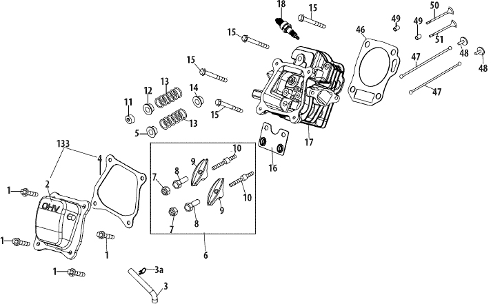
| Ref. | Part No. | Description |
|---|---|---|
| 1 | 710-04744 | Bolt M6×16 |
| 2 | 951-11054 | Valve Cover |
| 3 | 731-07059 | Breather Hose |
| 3a | 726-04101 | Hose Clamp |
| 4 | 951-11565 | Valve Cover Gasket |
| 5 | 951-12000 | Retainer, In.Valve Spring |
| 6 | 951-11892 | Rocker Arm Assembly |
| 7 | 751-11124 | Nut, Pivot Locking |
| 8 | 751-11123 | Adjusting Nut,Valve |
| 9 | 951-11893 | Rocker Arm |
| 10 | 710-04902 | Bolt, Pivot |
| 11 | 951-12002 | Adjuster, Exh Valve |
| 12 | 951-12003 | Retainer, Ex.Valve Spring |
| 13 | 951-12004 | Valve Spring |
| 14 | 951-11894 | Intake Valve Seal |
| 15 | 710-04933 | Bolt M8x55 |
| 16 | 951-11895 | Push Rod Guide |
| 17 | 951-10722A | Cylinder Head Assembly (lncl.4,5,7-14,16,17,21, 29,30,46,50,51) |
| 18 | 951-10292 | Spark Plug/F6Rtc |
| 46 | 951-11898 | Gasket, Cylinder Head |
| 47 | 951-10648 | Push Rod Kit |
| 48 | 951-11899 | Tappet |
| 49 | 715-04090 | Dowel Pin, 10×16 |
| 50 | 951-10647A | Valve Kit |
| 51 | 951-10647A | Valve Kit |
| 133 | 951-11063A | Valve Cover Kit |
| 952Z265-SU-11 | Complete Engine | |
| 951-10661B | Gasket Kit - External (lncl.4,21,29-31,34,79) | |
| 951-11062B | Short Block (lncl.4,21,29,30,46,48, 49,52-55,58-81) | |
| 951-11061A | Gasket Kit - Complete (lncl.4,21,29-31,34,46, 60,61,70,76,79,80) |
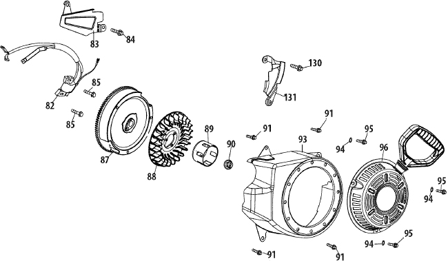
| Ref. | Part No. | Description |
|---|---|---|
| 82 | 951-10646 | Ignition Coil Assembly |
| 83 | 951-11110 | Air Flow Shield |
| 84 | 710-04940 | Bolt M6×10 |
| 85 | 710-04919 | Bolt M6×25 |
| 87 | 951-12416 | Flywheel |
| 88 | 951-10909 | Fan, Cooling |
| 89 | 951-10911 | Pulley, Starter |
| 90 | 712-04209 | Nut, Special?M14×1.5 |
| 91 | 710-04915 | Bolt M6×12 |
| 93 | 951-10663A | Blower Housing |
| 94 | 736-04455 | Gasket 6 |
| 95 | 710-04974 | Bolt M6×10 |
| 96 | 951-10658 | Recoil Starter |
| 96 | 731-05696 | Recoil Starter Handle |
| 130 | 710-04979 | Bolt M6×18 |
| 131 | 951-11109 | Blower Housing Shield |
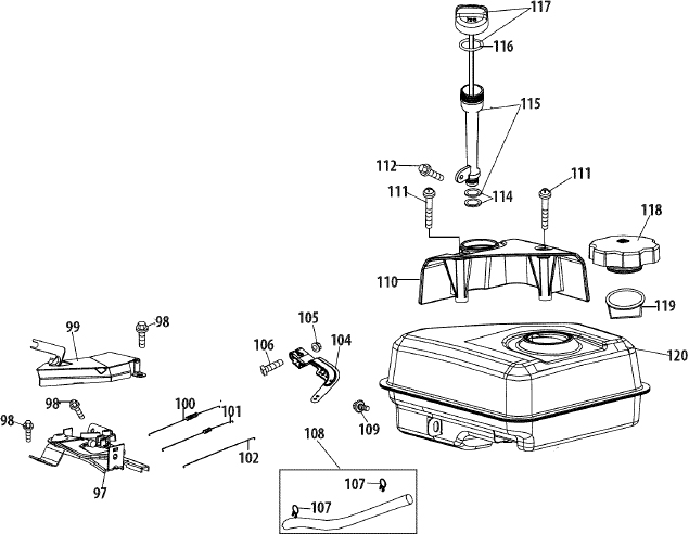
| Ref. | Part No. | Description |
|---|---|---|
| 97 | 951-10758 | Primer Bracket |
| 98 | 710-04928 | Bolt M6x12 |
| 99 | 951-11108 | Governor System Shield |
| 100 | 951-11935 | Governor Spring |
| 101 | 951-10664 | Throttle Linkage Spring |
| 102 | 951-10665 | Throttle Linkage |
| 104 | 951-11106 | Governor Arm |
| 105 | 712-04212 | Nut M6 |
| 106 | 710-04908 | Governor Arm Bolt |
| 107 | 951-11700 | Fuel Hose Clamp |
| 108 | 951-10650 | Fuel Line Kit |
| 109 | 710-04915 | Bolt M6×12 |
| 110 | 951-10662 | Dipstick Decoration Cover |
| 111 | 710-04905 | Bolt |
| 112 | 710-04915 | Bolt M6×12 |
| 114 | 951-11381 | Oil Fill Tube O-Ring |
| 115 | 951-11913 | Oil Fill Tube Assembly |
| 116 | 951-11904 | Dipstick O-Ring |
| 117 | 951-12482 | Dipstick Assembly |
| 118 | 951-10649A | Fuel Cap Assembly |
| 119 | 951-11933 | Fuel Level Indicator |
| 120 | 951-10653B | Fuel Tank Assembly |
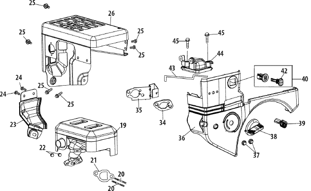
| Ref. | Part No. | Description |
|---|---|---|
| 19 | 951-11282 | Muffler Assembly |
| 20 | 710-04911 | Muffler Stud M8×36 |
| 20 | 951-10657 | Muffler Stud Assembly |
| 21 | 951-11285 | Muffler Gasket |
| 22 | 712-04214 | Nut, M8 |
| 23 | 951-11111 | Exhaust Pipe Shield |
| 24 | 710-04914 | Bolt M6×10 |
| 25 | 710-04915 | Bolt M6×12 |
| 26 | 951-10642A | Muffler Shield |
| 34 | 951-11897 | Carburetor Gasket Plate |
| 35 | 951-11112 | Choke Control |
| 36 | 951-10634 | Air Cleaner Housing |
| 37 | 712-04213 | Nut |
| 38 | 951-11284 | Choke Knob |
| 39 | 951-10757 | Throttle Control Knob |
| 40 | 951-10637 | Key Switch |
| 42 | 731-05632 | Key |
| 43 | 951-10640 | Choke Push Rod |
| 44 | 951-10635 | Heater Box |
| 45 | 710-04919 | Bolt M6×25 |
NOTES
MTD CONSUMER GROUP INC (MTD), the California Air Resources Board (CARB) and the United States Environment Protection Agency (U. S. EPA)
Emission Control System Warranty Statement
(Owner’s Defect Warranty Rights and Obligations)
EMISSION CONTROL SYSTEM COVERAGE IS APPLICABLE TO CERTIFIED ENGINES PURCHASED IN CALIFORNIA IN 2005 AND THERE AFTER, WHICH ARE USED IN CALIFORNIA, AND TO CERTIFIED MODEL YEAR 2005 AND LATER ENGINES WHICH ARE PURCHASED AND USED ELSEWHERE IN THE UNITED STATES.
California and elsewhere in the United States Emission Control Defects Warranty Coverage
The California Air Resources Board (CARB), U. S. EPA and MTD are pleased to explain the emissions control system warranty on your model year 2006 and later small off-road engine. In California, new small off-road engines must be designed, built and equipped to meet the States anti-smog standards. Elsewhere in the United States, new non-road, spark-ignition engines certified for model 2005 and later, must meet similar standards set forth by the U. S. EPA. MTD must warranty the emission control system on your engine for the period of time listed below, provided there has been no abuse, neglect or improper maintenance of your small off-road engine.
Your emission control system may include parts such as the carburetor, fuel-injection system, the ignition system, and catalytic converter, fuel tanks, fuel lines, fuel caps, valves, canisters, filters, vapor hoses, clamps, connectors, and other associated emission-related components.
Where a warrantable condition exists, MTD will repair your small off-road engine at no cost to your including diagnosis, parts and labor.
MANUFACTURER’S WARRANTY COVERAGE:
This emissions control system is warranted for two years. If any emission-related part on your engine is defective, the part will be repaired or replaced by MTD.
OWNER’S WARRANTY RESPONSIBILITIES:
As the small off-road engine owner, you are responsible for the performance of the required maintenance listed in your Owner’s Manual. MTD recommends that you retain all your receipts covering maintenances on your small off-road engine, but MTD can not deny warranty solely for the lack of receipts or for your failure to ensure the performance to all scheduled maintenance.
As the small off-road engine owner, you should however be aware that MTD may deny your warranty coverage if your small off-road engine or part has failed due to abuse, neglect, improper maintenance or unapproved modifications.
You are responsible for presenting your small off-road engine to an Authorized MTD Service Dealer as soon as a problem exists. The warranted repairs should be completed in a reasonable amount of time, not to exceed 30 days.
If you have any questions regarding your warranty rights and responsibilities, you should contact a MTD Service Representative at 1-800-800-7310 and address is MTD CONSUMER GROUP, P.O. Box 361131, Cleveland OH, 44136-0019.
DEFECTS WARRANTY REQUIREMENTS FOR 1995 AND LATER SMALL OFF-ROAD ENGINES:
This section applies to 1995 and later small off-road engines. The warranty period begins on the date the engine or equipment is delivered to an ultimate purchaser.
(a) General Emissions Warranty Coverage
MTD must warrant to the ultimate purchaser and each subsequent purchaser that the engine is:
- Designed, built, and equipped so as to conform with all applicable regulations adopted by the Air Resources Board pursuant to its authority in Chapters 1 and 2,Part 5, Division 26 of the Health and Safety Code; and
- Free from defects in materials and workmanship that cause the failure of a warranted part to be identical in all material respects to the part as described in the engine manufacturer’s application for certification for a period of two years.
(b) The warranty on emissions-related parts will be interpreted as follows:
- Any warranted part that is not scheduled for replacement as required maintenance in the written instructions required by Subsection (c) must be warranted for the warranty period defined in Subsection (a)(2). If any such part fails during the period of warranty coverage, it must be repaired or replaced by MTD according to Subsection (4) below. Any such part repaired or replaced under the warranty must be warranted for the remaining warranty period.
- Any warranted part that is scheduled only for regular inspection in the written instructions required by Subsection (c) must be warranted for the warranty period defined in Subsection (a)(2). A statement in such written instructions to the effect of “repair or replace as necessary” will not reduce the period of warranty coverage. Any such part repaired or replaced under warranty must be warranted for the remaining warranty period.
- Any warranted part that which is scheduled for replacement as required maintenance in the written instructions required by Subsection (c) must be warranted for the period of time prior to the first scheduled replacement point for that part. If the part fails prior to the first scheduled replacement, the part must be repaired or replaced by MTD according to Subsection (4) below. Any such part repaired or replaced under warranty must be warranted for the remainder of the period prior to the first scheduled replacement point for the part.
- Repair or replacement of any warranted part under the warranty provisions of this article must be performed at no charge to the owner at a warranty station.
- Notwithstanding the provisions of Subsection (4) above, warranty services or repairs must be provided at all MTD distribution centers that are franchised to service the subject engines.
- The owner must not be charged for diagnostic labor that leads to the determination that a warranted part is in fact defective, provided that such diagnostic work is performed at a warranty station.
- The engine manufacturer is liable for damages to other engine components proximately caused by a failure under warranty of any warranted part.
- Throughout the engine’s warranty period defined in Subsection (a)(2), MTD will maintain a supply of warranted parts sufficient to meet the expected demand for such parts.
- Any replacement part may be used in the performance of any warranty maintenance or repairs and must be provided without charge to the owner. Such use will not reduce the warranty obligations of MTD.
- Add-on or modified parts that are not exempted by the Air Resources Board may not be used. The use of any non-exempted add-on or modified parts shall be grounds for disallowing a warranty claim made in accordance with this article. The engine manufacturer shall not be liable under this article to warrant failures of warranted parts caused by the use of non-exempted add-on or modified part.
(c) MTD will include a copy of the following emission warranty parts list with each new engine, using those portions of the list applicable to the engine.
- Fuel Metering System
- Cold start enrichment system (soft choke)
- Carburetor and internal parts
- Fuel Pump
- Fuel Tank
- Air Induction System
- Air cleaner
- Intake manifold
- Ignition System
- Spark plug(s)
- Magneto Ignition System
- Exhaust System
- Catalytic converter
- SAI (Reed valve)
- Miscellaneous Items Used in Above System
- Vacuum, temperature, position, time sensitive valves and switches
- Connectors and assemblies
- Evaporative control
- Fuel Hose certified for ARB evaporative emission of 2006.
- Fuel Hose Clamps
- Tethered fuel cap
- Carbon canister
- Vapor lines
GDOC-100174 Rev.B
Look For Relevant Emissions Durability Period and Air Index Information On Your Engine Emissions Label
Engines that are certified to meet the California Air Resources Board (CARB) Tier 2 Emission Standards must display information regarding the Emissions Durability Period and the Air Index. Sears Brands Management Corporation makes this information available to the consumer on our emission labels.
The Emissions Durability Period describes the number of hours of actual running time for which the engine is certified to be emissions compliant, assuming proper maintenance in accordance with the Operating & Maintenance Instructions. The following categories are used:
| Moderate: | Engine is certified to be emission compliant for 125 hours of actual engine running time. |
|---|---|
| Intermediate: | Engine is certified to be emission compliant for 250 hours of actual engine running time. |
| Extended: | Engine is certified to be emission compliant for 500 hours of actual engine running time. |
For example, a typical walk-behind lawn mower is used 20 to 25 hours per year. Therefore, the Emissions Durability Period of an engine with an intermediate rating would equate to 10 to 12 years.
The Air Index is a calculated number describing the relative level of emissions for a specific engine family. The lower the Air Index, the cleaner the engine. This information is displayed in graphical form on the emissions label.
After July 1, 2000, Look For Emissions Compliance Period On Engine Emissions Compliance Label
After July 1, 2000 certain Sears Brands Management Corporation engines will be certified to meet the United States Environmental Protection Agency (USEPA) Phase 2 emission standards. For Phase 2 certified engines, the Emissions Compliance Period referred to on the Emissions Compliance label indicates the number of operating hours for which the engine has been shown to meet Federal emission requirements.
For engines less than 225 cc displacement, Category C = 125 hours, B = 250 hours and A = 500 hours.
For engines of 225 cc or more, Category C = 250 hours, B = 500 hours and A = 1000 hours.
This is a generic representation of the emission label typically found on a certified engine.
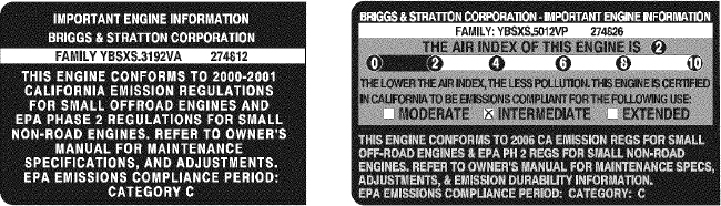
GDOC-100182 Rev. B
REPAIR PROTECTION AGREEMENT
Congratulations on making a smart purchase. Your new Craftsman® product is designed and manufactured for years of dependable operation. But like all products, it may require repair from time to time. That’s when having a Repair Protection Agreement can save you money and aggravation.
Here’s what the Repair Protection Agreement* includes:
 |
Expert service by our 10,000 professional repair specialists |
|---|---|
|
Unlimited service and no charge for parts and labor on all covered repairs |
|
Product replacement up to $1500 if your covered product can’t be fixed |
|
Discount of 25% from regular price of service and related installed parts not covered by the agreement; also, 25% off regular price of preventive maintenance check |
|
Fast help by phone - we call it Rapid Resolution - phone support from a Sears representative. Think of us as a “talking owner’s manual.” |
Once you purchase the Repair Protection Agreement, a simple phone call is all that it takes for you to schedule service. You can call anytime day or night, or schedule a service appointment online.
The Repair Protection Agreement is a risk-free purchase. If you cancel for any reason during the product warranty period, we will provide a full refund. Or, a prorated refund anytime after the product warranty period expires. Purchase your Repair Protection Agreement today!
Some limitations and exclusions apply. For prices and additional information in the U.S.A. call 1-800-827-6655.
*Coverage in Canada varies on some items. For full details call Sears Canada at 1-800-361-6665.
Sears Installation Service
For Sears professional installation of home appliances, garage door openers, water heaters, and other major home items, in the U.S.A. or Canada call 1-800-4-MY-HOME®.
ÍNDICE
- Declaración de garantía
- Prácticas operación seguras
- Montaje
- Operación
- Servicio y Mantenimiento
- Almacenamiento fuera de temporada
- Solución de problemas
- Acuerdo de protección para reparaciones
- Lista de piezas
- Número de servicio
DECLARACIÓN DE GARANTÍA
GARANTÍA COMPLETA CRAFTSMAN POR DOS AÑOS
POR DOS AÑOS a partir de la fecha de la compra, este producto está garantizado por defectos en los materiales y la mano de obra. Los productos defectuosos serán reparados sin costo o reemplazados sin costo si la reparación no está disponible.
La presente garantía se anula si se utiliza este producto alguna vez para prestar servicios comerciales o si se lo alquila a otra persona.
Para obtener información sobre el alcance de la garantía y solicitar la reparación o el reemplazo, visite el sitio Web: www.craftsman.com
Esta garantía cubre ÚNICAMENTE los defectos en los materiales y en la mano de obra. Esta garantía NO cubre:
- Elementos no renovables que pueden desgastarse por el uso normal, durante el plazo de la garantía, incluyendo entre otros, las barrenas, las paletas de las barrenas, los cortadores de desplazamiento, las zapatas antideslizantes, la placa de raspado, los pasadores de cuchilla, la bujía, el filtro de aire, las correas y el filtro de aceite.
- Servicios de mantenimiento estándar, cambios de aceite o afinación.
- Cambio de neumáticos o reparaciones por pinchaduras con objetos externos como clavos, espinas, tocones o vidrios.
- Reemplazo o reparación de neumáticos o ruedas como resultado del desgaste normal, un accidente, o funcionamiento o mantenimiento incorrectos.
- Reparaciones requeridas como resultado del uso inadecuado por parte del operador, incluyendo entre otros el daño ocasionado por objetos que impactan la máquina y que tuercen el bastidor, el eje de la barrena, etc., o debido a que el motor fue acelerado en exceso.
- Reparaciones necesarias debido a negligencia del operador, incluyendo entre otros, daños mecánico y eléctrico ocasionado por un almacenamiento no apropiado, falla por el uso de aceite de grado y/o cantidad no apropiados o falla por no dar mantenimiento al equipo de acuerdo con las instrucciones contenidas en el manual del operador.
- Limpieza o reparaciones del motor (sistema de combustible) debidas a combustible que se determina está contaminado u oxidado (viejo). En general, el combustible debe utilizarse en un período no mayor de 30 días a partir de su adquisición.
- El deterioro y desgaste normal de los acabados exteriores, o reemplazo de la etiqueta del producto.
Esta garantía le otorga derechos legales específicos, pero usted podría gozar de otros derechos en razón de su lugar de residencia.
Sears Brands Management Corporation, Hoffman Estates, IL 60179
ESPECIFICACIONES DEL PRODUCTO
| Tipo de aceite del motor: | 5W-30 |
|---|---|
| Capacidad de aceite del motor: | 20 onzas |
| Capacidad de combustible: | 2.3 cuartos |
| Bujías: | F6RTC (951-10292) |
| Separación de las bujías: | .020” a .030” |
NÚMERO DE MODELO
Número de modelo ..........................................................
Número de serie ..........................................................
Fecha de compra ..........................................................
Registre arriba el número del modelo, el número de serie y la fecha de compra
INSTRUCCIONES DE SEGURIDAD
ADVERTENCIALa presencia de este símbolo indica que se trata de instrucciones importantes de seguridad que se deben respetar para evitar poner en peligro su seguridad personal y/o material y la de otras personas. Lea y siga todas las instrucciones de este manual antes de poner en funcionamiento esta máquina. Si no respeta estas instrucciones podría provocar lesiones personales. Cuando vea este símbolo, ¡preste atención a la advertencia!
ADVERTENCIAPROPOSICIÓN 65 DE CALIFORNIA
El escape del motor de este producto, algunos de sus componentes y algunos componentes del vehículo contienen o liberan sustancias químicas que el estado de California considera que pueden producir cáncer, defectos de nacimiento u otros problemas reproductivos.
PELIGROEsta máquina fue construida para ser operada de acuerdo con las reglas de seguridad contenidas en este manual. Al igual que con cualquier tipo de equipo motorizado, un descuido o error por parte del operador puede producir lesiones graves. Esta máquina es capaz de amputar manos y pies y de arrojar objetos con gran fuerza. De no respetar las instrucciones de seguridad siguientes se pueden producir lesiones graves o la muerte.
ADVERTENCIASu responsabilidad— Restrinja el uso de esta máquina motorizada a las personas que lean, comprendan y respeten las advertencias e instrucciones que aparecen en este manual y en la máquina.
¡GUARDE ESTAS INSTRUCCIONES!
CAPACITACIÓN
- Lea, entienda y cumpla todas las instrucciones incluidas en la máquina y en los manuales antes de montarla y utilizarla. Guarde este manual en un lugar seguro para consultas futuras y periódicas, así como para solicitar repuestos.
- Lea el Manual del Operador y siga todas las advertencias e instrucciones de seguridad. El fracaso de hacer así puede causar la herida seria al operador y/o personas presentes.
- Familiarícese con todos los controles y con el uso adecuado de los mismos. Sepa cómo detener la máquina y desactivar los controles rápidamente.
- No permita nunca que los niños menores de 14 años utilicen esta máquina. Los niños de 14 años en adelante deben leer y entender las instrucciones de operación y normas de seguridad contenidas en este manual, y en la máquina ydeben ser entrenados y supervisados por un adulto.
- Nunca permita que los adultos operen esta máquina sin recibir antes la instrucción apropiada.
- Los objetos arrojados por la máquina pueden producir lesiones graves. Planifique el patrón en el que va a ir arrojando nieve para evitar que la descarga de material se realice hacia los caminos, los observadores, etc.
- Mantenga a los observadores, ayudantes, mascotas y niños por lo menos a 75 pies de la máquina mientras la misma está en funcionamiento. Detenga la máquina si alguien se acerca.
- Sea precavido para evitar patinarse o caerse especialmente cuando opera la máquina en reversa.
PREPARATIVOS
Inspeccione minuciosamente el área donde utilizará el equipo. Saque todos los felpudos, periódicos, trineos, tablas, cables y otros objetos extraños con los que podría tropezar o que podrían ser arrojados por la barrena / impulsor.
- Para protegerse los ojos utilice siempre anteojos o antiparras de seguridad mientras opera la máquina o mientras la ajusta o repara. Los objetos arrojados que rebotan pueden producir lesiones oculares graves.
- No opere la máquina sin la vestimenta adecuada para estar al aire libre en invierno. No utilice alhajas, bufandas largas u otras prendas sueltas que podrían enredarse en las partes móviles. Utilice un calzado especial para superficies resbaladizas.
- Use un prolongador y un tomacorriente de tres cables con conexión a tierra para todas las máquinas con motores de encendido eléctrico.
- Ajuste la altura de la caja del tomacorriente para limpiar la grava o las superficies con piedras trituradas.
- Desengrane todas las palancas de control antes de arrancar el motor.
- Nunca intente realizar ajustes mientras el motor está en marcha excepto en los casos específicamente recomendados en el manual del operador.
- Deje que el motor y la máquina se adapten a la temperatura exterior antes de comenzar a sacar la nieve.
Manejo seguro de la gasolina
Para evitar lesiones personales o daños materiales tenga mucho cuidado cuando trabaje con gasolina. La gasolina es sumamente inflamable y sus vapores pueden causar explosiones. Si se derrama gasolina encima o sobre la ropa se puede lesionar gravemente ya que se puede incendiar. Lávese la piel y cámbiese de ropa de inmediato.
- Utilice sólo los recipientes para gasolina autorizados.
- Apague todos los cigarrillos, cigarros, pipas y otras fuentes de combustión.
- Nunca cargue combustible en la máquina en un espacio cerrado.
- Nunca saque la tapa del combustible ni agregue combustible mientras el motor está caliente o en marcha.
- Deje que el motor se enfríe por lo menos dos minutos antes de volver a cargar combustible.
- Nunca llene en exceso el depósito de combustible. Llene el tanque a no más de ½ pulgada por debajo de la base del cuello de llenado dejando espacio para la dilatación del combustible.
- Vuelva a colocar la tapa de la gasolina y ajústela bien.
- Limpie el combustible que se haya derramado sobre el motor y el equipo. Traslade la máquina a otra zona. Espere 5 minutos antes de encender el motor.
- Nunca almacene la máquina o el recipiente de combustible en un espacio cerrado donde haya fuego, chispas o luz piloto (por ejemplo, hornos, calentadores de agua, calefactores, secadores de ropa, etc.).
- Deje que la máquina se enfríe por lo menos 5 minutos antes de guardarla.
- Nunca llene los recipientes en el interior de un vehículo o camión o caja de remolque con recubrimientos plásticos. Coloque siempre los recipientes en el piso y lejos del vehículo antes de llenarlos.
- Si es posible, retire el equipo a gasolina del camión o remolque y llénelo en el suelo. Si esto no es posible, llene el equipo en un remolque con contenedor portátil, en vez de desde una boquilla dispensadora de gasolina.
- Mantenga la boquilla dispensadora en contacto con el borde del depósito de combustible o con la abertura del recipiente en todo momento, hasta terminar la carga. No utilice un dispositivo de apertura/cierre de boquilla.
FUNCIONAMIENTO
- No ponga las manos o los pies cerca de las piezas rotatorias, en la caja de la barrena / impulsor o en el montaje del canal de descarga. Hacer contacto con piezas giratorias puede resultar en la amputación de manos o pies.
- La palanca de control de la barrena / impulsor es un dispositivo de seguridad. Nunca evite su funcionamiento. De hacerlo la operación de la máquina es riesgosa y puede ocasionar lesiones.
- Las palancas de control deben funcionar bien en ambas direcciones y regresar automáticamente a la posición de desengrane cuando se las suelta.
- Nunca opere la máquina si falta un montaje del canal o si el mismo está dañado. Mantenga todos los dispositivos de seguridad en su lugar y en funcionamiento.
- Nunca encienda el motor en espacios cerrados o en una zona con poca ventilación. El escape del motor contiene monóxido de carbono, un gas inodoro y letal.
- No utilice la máquina bajo la influencia del alcohol o las drogas.
- El silenciador y el motor se calientan y pueden causar quemaduras. No los toque. Mantenga a los niños alejados.
- Sea sumamente precavido cuando opere la máquina sobre una superficie con grava o cuando la cruce. Manténgase alerta por si se presentan peligros ocultos o tránsito.
- Tenga cuidado cuando cambie de dirección o cuando opere la máquina en pendientes. No use la máquina en pendientes pronunciadas.
- Planifique el patrón en el que va a ir arrojando nieve para evitar que la descarga de material se produzca hacia las ventanas, las paredes, los automóviles, etc. y evitar así posibles daños materiales o lesiones producidas por los rebotes.
- Nunca dirija la descarga hacia los niños, los observadores o las mascotas ni deje que nadie se pare delante de la máquina.
- No sobrecargue la capacidad de la máquina tratando de sacar la nieve muy rápidamente.
- Nunca opere esta máquina sin buena visibilidad o iluminación. Siempre debe estar seguro de que está bien afirmado y sujetando firmemente las manijas. Camine, nunca corra.
- Corte la corriente a la barrena / impulsor cuando transporte la máquina o cuando la misma no está en uso.
- Nunca opere la máquina a alta velocidad de desplazamiento sobre superficies resbaladizas. Mire hacia abajo y hacia atrás y tenga cuidado cuando vaya marcha atrás.
- Si la máquina comenzara a vibrar de manera anormal, detenga el motor, desconecte el cable de la bujía y póngala de manera que haga masa contra el motor. Inspeccione la máquina minuciosamente para ver si está dañada. Repare todos los daños antes de encender y operar la máquina.
- Desengrane todas las palancas de control y detenga el motor antes de dejar la posición de operación (detrás de las manijas). Espere a que la barrena / impulsor se detenga por completo antes de destapar el montaje del canal o realizar ajustes e inspecciones.
- Nunca ponga las manos en las aberturas de descarga o de recolección. Utilice siempre la herramienta de limpieza que se adjunta para destapar la abertura de descarga. No destape el montaje del canal mientras el motor está en funcionamiento. Antes de destaparlo, apague el motor y permanezca detrás de las manijas hasta que todas las partes móviles se hayan detenido.
- Use sólo uniones y accesorios aprobados por el fabricante (por ejemplo, pesas para las ruedas, cadenas para los neumáticos, cabinas, etc.).
- Para encender el motor, jale de la cuerda lentamente hasta que sienta resistencia, luego jale rápidamente. El repliegue rápido de la cuerda de arranque (tensión de retroceso) le jalará la mano y el brazo hacia el motor más rápido de lo que usted puede soltar. El resultado pueden ser huesos rotos, fracturas, hematomas o esguinces.
- Si se presentan situaciones que no están previstas en este manual, sea cuidadoso y use el sentido común.
- Por razones de seguridad dentro de la garantía, operación o mantenimiento de las preguntas, o para pedir piezas y el servicio de horario, llame al 1-800-4-MY-HOME.
MANTENIMIENTO Y ALMACENAMIENTO
- Nunca altere los dispositivos de seguridad. Controle periódicamente que funcionen correctamente. Remítase a las secciones de mantenimiento y ajuste de este manual.
- Antes de realizar la limpieza, reparar o revisar la máquina, desengrane todas las palancas de control y detenga el motor. Espere a que la barrena / impulsor se detenga por completo. Desconecte el cable de la bujía y póngalo haciendo masa contra el motor para evitar que se encienda accidentalmente.
- Controle frecuentemente que todos los pernos y tornillos estén bien ajustados para comprobar que la máquina se encuentra en condiciones seguras de funcionamiento. Además, haga una inspección visual de la máquina para verificar si está dañada.
- No cambie la configuración del regulador del motor ni acelere demasiado el mismo. El regulador del motor controla la velocidad máxima segura de funcionamiento del motor.
- Las placas de raspado y las zapatas antideslizantes que se usan con la máquina quitanieve se desgastan y se dañan. Para proteger su seguridad, verifique frecuentemente todos los componentes y reemplácelos sólo con partes de los fabricantes de equipos originales (OEM). ¡El uso de piezas que no cumplen con las especificaciones del equipo original puede resultar en rendimiento inadecuado además de poner en riesgo la seguridad!
- Revise las palancas de control periódicamente para verificar que engranen y desengranen adecuadamente y ajústelos si es necesario. Consulte la sección de ajustes de este manual del operador para obtener instrucciones.
- Mantenga o reemplace las etiquetas de seguridad e instrucciones según sea necesario.
- Respete las normas referentes a la disposición correcta y las reglamentaciones sobre gasolina, aceite, etc. para proteger el medio ambiente.
- Antes de almacenar la máquina enciéndala unos minutos para sacar la nieve que haya quedado en la misma y para evitar así que se congele la barrena / impulsor.
- Según la Comisión de Seguridad de Productos para el Consumidor de los Estados Unidos (CPSC) y la Agencia de Protección Ambiental de los Estados Unidos (EPA), este producto tiene una vida útil media de siete (7) años, ó 60 horas de funcionamiento. Al finalizar la vida útil media, adquiera una máquina nueva o haga inspeccionar anualmente ésta por un distribuidor de servicio autorizado para cerciorarse de que todos los sistemas mecánicos y de seguridad funcionan correctamente y no tienen excesivo desgaste. Si no lo hace, pueden producirse accidentes, lesiones o muerte
- Nunca almacene la máquina o el recipiente de combustible en un espacio cerrado donde haya fuego, chispas o luz piloto como por ejemplo, calentadores de agua, hornos, secadores de ropa, etc.
- Consulte siempre el manual del operador para obtener instrucciones adecuadas para el almacenamiento fuera de temporadaVerifique frecuentemente la línea de combustible, el tanque, el tapón, y los accesorios buscando rajaduras o pérdidas. Reemplace de ser necesario.
- No dé arranque al motor si no está la bujía de encendido.
NO MODIFIQUE EL MOTOR
Para evitar lesiones graves o la muerte, no modifique el motor bajo ninguna circunstancia. Si cambia la configuración del regulador el motor puede descontrolarse y operar a velocidades inseguras. Nunca cambie la configuración de fábrica del regulador del motor.
AVISO REFERIDO A EMISIONES
Los motores que están certificados y cumplen con las regulaciones de emisiones federales EPA y de California para SORE (Equipos pequeños todo terreno) están certificados para operar con gasolina común sin plomo y pueden incluir los siguientes sistemas de control de emisiones: Modificación de motor (EM) y catalizador de tres vías (TWC) si están equipados de esa manera.
GUARDACHISPAS
ADVERTENCIAEsta máquina está equipada con un motor de combustión interna y no debe ser utilizada en o cerca de un terreno agreste cubierto por bosque, malezas o hierba excepto si el sistema de escape del motor está equipado con un amortiguador de chispas que cumpla con las leyes locales o estatales correspondientes, en caso de haberlas.
Si se utiliza un amortiguador de chispas el operador lo debe mantener en condiciones de uso adecuadas. En el Estado de California las medidas anteriormente mencionadas son exigidas por ley (Artículo 4442 del Código de Recursos Públicos de California). Es posible que existan leyes similares en otros estados. Las leyes federales se aplican en territorios federales.
Puede conseguir el amortiguador de chispas para el silenciador a través de su distribuidor autorizado de motores o poniéndose en contacto con el departamento de servicios.
SÍMBOLOS DE SEGURIDAD
Esta página describe los símbolos y figuras de seguridad internacionales que pueden aparecer en este producto. Lea el manual del operador para obtener la información terminada sobre seguridad, reunirse, operación y mantenimiento y reparación.
| Símbolo | Descripción |
|---|---|
 |
LEA EL MANUAL DEL OPERADOR (S) Lea, entienda, y siga todas las instrucciones en el manual (es) antes de intentar reunirse y funcionar. |
 |
LA ADVERTENCIA — PLATOS ROTATORIOS Guarde manos de entrada y aperturas de la descarga mientras la máquina corre. Allí ellos hacen para girar platos dentro. |
 |
LA ADVERTENCIA — LÁMINAS ROTATIVAS Guarde manos de entrada y aperturas de descarga mientras la máquina corre. Allí hacen girar láminas dentro. |
 |
LA ADVERTENCIA — TALADRO ROTATIVO No ponga manos o pies cerca del giro de partes, en el alojamiento de taladro/aspa o asamblea de tolva. Contacto con las partes rotativas puede amputar manos y pies. |
 |
OBJETOS LANZADOS POR ADVERTENCIA Esta máquina puede recoger y lanzar objetos que pueden causar la herida personal seria. |
 |
GASOLINA DE ADVERTENCIA ES INFLAMABLE Permita que el motor se enfríe al menos dos minutos antes del reabastecimiento de combustible. |
 |
ADVERTENCIA — MONÓXIDO DE CARBONO Nunca dirijas un motor dentro o en un área mal ventilada. Los gases de combustión de motor contienen el monóxido de carbono, un gas inodoro y mortal. |
 |
ADVERTENCIA — ELECTROCHOQUE No use el juez de salida eléctrico del motor en la lluvia. |
MONTAJE
NOTA: las referencias al lado derecho o y ciertos de la máquina quitanieve se determinan desde la parte posterior de la unidad en posición de operación (permaneciendo directamente detrás de la máquina quitanieve, mirando hacia el panel de la manija).
EXTRACCIÓN DE LA UNIDAD DE LA CAJA
- Corte las esquinas de la caja de cartón y extiéndala en el piso Quite y descarte todos los Insertos de empaque.
- Saque la máquina quitanieve de la caja.
- Asegúrese de vaciar completamente la caja antes de tirarla.
PARTES SUELTAS
Con el panel de carrera se Incluyen dos pasadores de cuchilla de barrena de repuesto. Consulte la sección “Barrenas” en la sección de Servicio y Mantenimiento para obtener más información sobre el reemplazo de los pasadores de cuchilla de barrena.
MONTAJE
- Coloque la palanca de cambios en la posición de avance (F) 6.
- Observe el área Inferior trasera de la máquina quitanieve para asegurarse de que ambos cables estén alineados con las guías rotatorias antes de girar la manija hacia arriba. Vea la figura 1.
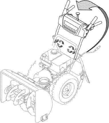
Figura 1
NOTA: Asegúrese de que los extremos superiores de cada cable están correctamente asentados en su soporte.
- Asegure la manija ajustando la perilla a mariposa de plástico situada en los lados Izquierdo y derecho de dicha manija. Vea la figura 2. Retire y descarte todos las bandas de plástico, si Las hubiera. Únicamente se utilizan para el empaque.
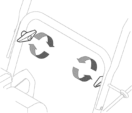
Figura 2
- Sitúe el montaje del canal sobre la base. Vea la figura 3.
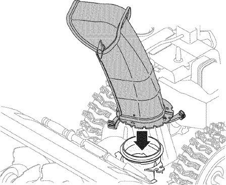
Figura 3
- Cierre los fijadores de la brida para asegurar el montaje del canal a la base del canal. Vea la figura 4. Los fijadores de la brida emiten un chasquido cuando están bien asegurados.
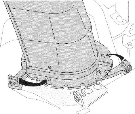
Figura 4
NOTA: si los fijadores de la brida no se ajustan en su lugar fácilmente, utilice la palma de su mano para aplicar una presión rápida y firme en la parte posterior de cada uno.
6.
- Quite la arandela plana y el broche de horquilla del extremo del control direccional del canal.
- Inserte el extremo del control direccional del canal en el soporte Inferior y asegúrelo mediante la arandela plana y el broche de horquilla que acaba de retirar. Vea la figura 5. Si es necesario, puede ajustarse el soporte Inferior. Consulte “Ajuste del soporte del canal” en la sección de Servicio y Mantenimiento.
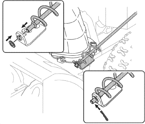
Figura 5
CONFIGURACIÓN
Herramienta de Limpieza del Canal
Hay una herramienta de limpieza del canal ¡ajustada a la parte superior de la caja de la barrena con un pasador de ensamblado. Vea la figura 6. La herramienta está diseñada para limpiar el hielo y la nieve del montaje de un canal. Este producto se sujeta mediante una unión de cable en la fábrica. Corte la unión de cable antes de operar la máquina quitanieve.
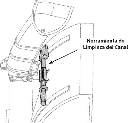
Figura 6
ADVERTENCIANunca use sus manos para liberar un montaje de canal tapado. Apague el motor y permanezca detrás de las manijas hasta que todas las partes móviles se hayan detenido antes de utilizar la herramienta de limpieza para limpiar el montaje del canal.
Presión de los neumáticos
ADVERTENCIABajo ninguna circunstancia no excedan del fabricante recomienda psi. La Igualdad de la presión de los neumáticos deben mantenerse en todo momento. Cuando la presión excesiva puede causar asientos bolas neumático / llanta de montaje para reventar con la fuerza suficiente para causar un daño grave. Se refieren a los flancos de los neumáticos de la presión recomendada.
Los neumáticos son demasiado Inflados para propósitos de envío. Revise la presión de los neumáticos antes de la nieve lanzador. Se refieren a la pared lateral del neumático para el fabricante de neumáticos recomendado psi y desinflar (o Inflar) los neumáticos, según sea necesario.
NOTA: La Igualdad de la presión de los neumáticos debe ser mantenida en todo momento para los efectos de la performance.
AJUSTES
Zapatas antideslizantes
Las zapatas antideslizantes de la máquina quitanieve se ajustan para arriba en fábrica para el envío. Si lo desea, puede ajustarlas hacia abajo antes de hacer funcionar la máquina quitanieve.
PRECAUCIÓNNo se recomienda que opere esta máquina quitanieve sobre grava, ya que es posible que la máquina quitanieve tome la grava suelta y la barrena la expulse, lo cual podría causar lesiones personales o dañar la máquina quitanieve.
- Si desea quitar nieve al ras del suelo, eleve más las zapatas antideslizantes en la caja de la barrena.
- Use las posiciones media o baja cuando la superficie que desee limpiar sea despareja, como un camino de grava.
NOTA: Si tiene que usar la máquina quitanieve sobre grava, mantenga la zapata antideslizante en la posición más elevada para lograr una separación máxima entre el piso y la placa de raspado.
Para ajustar las zapatas antideslizantes:
- Afloje las cuatros tuercas hexagonales (dos en cada lado) y los pernos del carro. Mueva las zapatas antideslizantes a la posición deseada. Vea la figura 7.
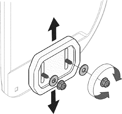
Figura 7
- Compruebe que toda la superficie Inferior de las zapatas antideslizantes esté contra el suelo para evitar un desgaste desparejo de los mismos.
- Vuelva a ajustar bien las tuercas y los pernos.
Ajuste del montaje del canal
Es posible ajustar la distancia a la cual se arroja la nieve cambiando el ángulo del montaje del canal. Para hacerlo:
- Detenga el motor quitando la llave de encendido y afloje la perilla a mariposa de plástico que se encuentra en el lado Izquierdo del montaje del canal.
- Gire el canal hacia arriba o hacia abajo antes de apretar la perilla a mariposa. Vea la figura 8.
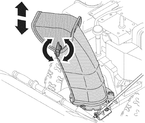
Figura 8
Prueba de control de la barrena
WARNINGAntes de operar su máquina quitanieve, lea atentamente y cumpla todas las Instrucciones que aparecen a continuación. Realice todos los ajustes para verificar que la máquina está operando con seguridad y correctamente.
Compruebe el ajuste del control de la barrena de la siguiente forma:
- Cuando se suelta el control de la barrena y está en posición desengranada arriba, el cable debe tener muy poco juego. NO debe estar tenso.
- En un área bien ventilada, arranque el motor de la máquina quitanieve según se Indica anteriormente en esta misma sección.
- Parado en la posición del operador (detrás de la máquina quitanieve), engrane la barrena.
- Deje la barrena engranada durante aproximadamente diez (10) segundos antes de soltar el control de la barrena. Repita esta operación varias veces.
- Con la barrena en posición desengranada arriba, camine al frente de la máquina.
- Confirme que la barrena ha dejado de girar por completo y no muestra NINGÚN signo de movimiento. Si la barrena muestra CUALQUIER signo de rotación, vuelva a la posición del operador y apague el motor Inmediatamente. Espere a que TODAS las partes móviles se detengan antes de volver a ajustar el control de la barrena.
- Para volver a ajustar el cable de control, afloje la tuerca hexagonal superior en la ménsula del cable de la barrena.
- Ubique la ménsula hacia arriba para brindar más juego (o hacia abajo para aumentar la tensión del cable). Vea la figura 9.
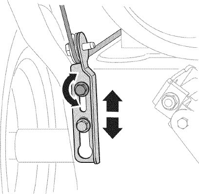
Figura 9
- Vuelva a apretar la tuerca hexagonal superior.
- Repita la prueba de control de la barrena para verificar que se ha logrado el ajuste adecuado.
OPERACIÓN
Ahora que ya ha ajustado su la máquina quitanieve para la operación, familiarícese con sus controles y características. Vea la Figura 10.
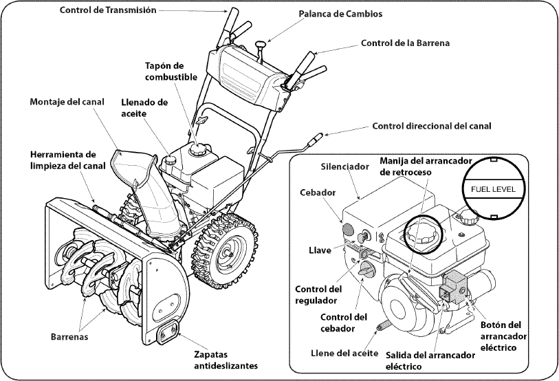
Figura 10
PALANCA DE CAMBIOS

La palanca de cambios está ubicada en el panel de carrera. Sitúe la palanca de cambios en cualquiera de las ocho posiciones para controlar la dirección del desplazamiento y la velocidad de piso.
Avance
Hay seis posiciones de avance (F). La posición uno (1) es la más lenta, y la posición seis (6) es la más rápida.
Retroceso
Hay dos velocidades de retroceso (R). La uno (1) es la más lenta, y la dos (2) es la más rápida.
LLAVE DE ENCENDIDO
La llave es un dispositivo de seguridad. Debe estar completamente insertada para que el motor arranque. Retire la llave cuando no use la máquina quitanieve.

NOTE: No gire la llave para intentar arrancar el motor. Al hacerlo podría romperla.

CONTROL DE OBTURACIÓN
El control de obturación se encuentra en la parte posterior del motor, y se activa haciendo girar el control de obturación a posición CHOKE.
Al activar el control de obturación se cierra la placa de obturación del carburador y se ayuda a encender el motor.

Cumple con los estándares de seguridad de ANSI
Las máquinas quitanieve de Craftsman cumplen con los estándares de seguridad del instituto estadounidense de estándares nacionales (ANSI).
CONTROL DEL REGULADOR
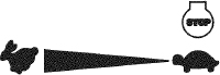
El control del regulador está ubicado en la parte trasera del motor. Regula la velocidad del motor, y lo apaga cuando se lo coloca en la posición STOP (detención).
CEBADOR
Al presionar el cebador se envía combustible directamente al carburador del motor para ayudar al encendido cuando el clima es frío.
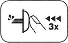
MANIJA DEL ARRANCADOR DE RETROCESO
Esta manija se utiliza para arrancar el motor manualmente.
BOTÓN DEL ARRANCADOR ELÉCTRICO
Si oprime el botón del arrancador eléctrico se engrana el arrancador eléctrico del motor cuando se lo enchufa a una fuente de energía de 120V.
SALIDA DEL ARRANCADOR ELÉCTRICO
Es necesario usar un cordón prolongador para exteriores de tres espigas y una fuente de energía / tomacorriente de pared de 120V.
BARRENA
Cuando están en granadas, la barrera giran y retiran la nieve al interior de la caja de la barrena.
MONTAJE DEL CANAL
La nieve retirada al interior de la caja de la barrena se descarga en el montaje del canal.
ZAPATAS ANTIDESLIZANTES
Ubique las zapatas antideslizantes en función de las condiciones de la superficie. Ajuste hacia arriba si la nieve está muy compactada. Ajústelas hacia abajo si usa la máquina en gravas o superficies con piedras trituradas.
CONTROL DE LA BARRENA
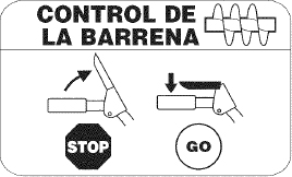
El control de la barrena está ubicado en la manija izquierda. Apriete la empuñadura de control contra la manija para engranar la barrena y empiece a quitar nieve. Suelte para que se detenga.
CONTROL DE LA TRANSMISIÓN/ CONTROL DE LA BARRENA DE CERRADURA
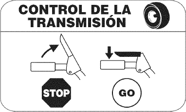
El control de transmisión está ubicado en la manija derecha. Presione la empuñadura de control contra la manija para engranar la rueda de transmisión. Suelte para que se detenga. El control de la transmisión también bloquea el control de la barrena de manera que puede operar el control direccional del canal sin interrumpir el proceso de quitar la nieve. Si el control de la barrena se engrana simultáneamente con el control de transmisión, el operador puede soltar el control de la barrena (en la manija izquierda) y las barrenas continuarán engranadas. Suelte ambos controles para detener tanto las barrenas como la transmisión de las ruedas.
NOTA: Suelte siempre el control de la transmisión antes de cambiar de velocidad. De no proceder así, aumentará el desgaste del sistema de transmisión de su máquina.
LLENADO DE ACEITE
Es posible controlar el nivel de aceite del motor, así como también agregar aceite, a través del llenado de aceite.
TAPÓN DE COMBUSTIBLE
Desenrosque el tapón de combustible para agregar gasolina al tanque de combustible.
CONTROL DIRECCIONAL DEL CANAL
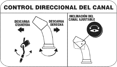
Para cambiar la dirección hacia la cual se arroja la nieve, gire el control direccional del canal.
HERRAMIENTA DE LIMPIEZA
ADVERTENCIANunca use sus manos para liberar un montaje de canal tapado. Antes de destaparlo, apague el motor y permanezca detrás de las manijas hasta que todas las partes móviles se hayan detenido.
La herramienta de limpieza del canal está ajustada convenientemente a la parte posterior de la caja de la barrena con un pasador de ensamblado. Si se acumulan nieve y hielo en el canal de descarga durante la operación, proceda como se indica a continuación para limpiar de manera segura el montaje del canal y la abertura del canal:
- Suelte el control de la barrena y el control de la transmisión.
- Para detener el motor saque la llave de encendido.
- Saque la herramienta de limpieza del pasador que la ajusta a la parte posterior de la caja de la barrena.
- Use el extremo con forma de pala de la herramienta de limpieza para desplazar y recoger la nieve y el hielo que se formaron cerca del conjunto del canal.
- Vuelva a ajustar la herramienta de limpieza al pasador de ensamblado ubicado en la parte posterior de la caja de la barrena, inserte de nuevo la llave de encendido y encienda el motor de la máquina quitanieve.
- Parado en la posición del operador (detrás de la máquina quitanieve), engrane el control de la barrena durante unos segundos para eliminar la nieve o el hielo que hayan quedado en el conjunto del canal.
ANTES DE ENCENDER EL MOTOR
ADVERTENCIALea, comprenda y siga todas las instrucciones y advertencias que aparecen en la máquina y en este manual antes de operarla.
Aceite
El motor se envió con aceite en el motor. Controle el nivel de aceite antes de cada operación para asegurarse de que haya aceite suficiente en el motor. Para obtener más instrucciones, remítase a los pasos que aparecen en la página 52.
NOTA: Asegúrese de comprobar el motor sobre una superficie nivelada y con el motor apagado.
- Retire el tapón de llenado / la varilla de medición de nivel de aceite y limpie la varilla.
- Inserte el tapón/ la varilla de medición en el cuello de llenado de aceite, pero no la atornille.
- Extraiga el tapón de llenado / la varilla de nivel de aceite. Si el nivel es bajo, agregue aceite (5W-30, con una clasificación mínima de SF/SG) lentamente hasta que el registro marque entre nivel alto (H) y bajo (L).
NOTA: No lo llene en exceso. El llenado excesivo de aceite puede hacer que el motor genere humo, que cueste arrancarlo o fallas en la bujía.
- Vuelva a colocar el tapón /la varilla de aceite y ajuste con firmeza antes de arrancar el motor.
Gasolina
Utilice gasolina para automóviles (sin plomo o con bajo contenido de plomo para minimizar los depósitos en la cámara de combustión) con un octanaje mínimo de 87. Se puede usar gasolina con hasta un 10% de etanol o un 15% de MTBE (éter metílico terciario-butílico). Nunca use una mezcla de aceite y gasolina ni gasolina sucia. Evite que se introduzca suciedad, polvo o agua en el tanque de combustible. NO utilice gasolina E85.
- Cargue combustible en un área bien ventilada y con el motor apagado. No fume ni permita llamas o chispas en el lugar donde se carga combustible o se encuentra el depósito de combustible del motor.
- No llene en exceso el tanque de combustible. Después de cargar combustible, asegúrese de que el tapón del tanque esté bien cerrado y asegurado.
- Tenga cuidado de no derramar combustible al realizar la recarga. El combustible derramado o sus vapores se pueden incendiar. Si se derrama combustible, asegúrese de que el área esté seca antes de arrancar el motor.
- Evite el contacto repetido o prolongado con la piel o inhalar los vapores.
ADVERTENCIATenga extremo cuidado cuando manipule gasolina. La gasolina es altamente inflamable y sus vapores pueden causar explosiones. Nunca agregue combustible a la máquina en interiores o mientras el motor está caliente o en funcionamiento. Apague los cigarrillos, cigarros, pipas y otras fuentes de combustión.
- Antes de sacar la tapa para cargar combustible, limpie alrededor.
- En el tanque de combustible hay un indicador de nivel. Llene el tanque hasta llegar al nivel de combustible del indicador. Vea la Figura 10. Tenga cuidado para no llenar el depósito en exceso.
ENCENDIDO DEL MOTOR
ADVERTENCIASiempre mantenga las manos y los pies alejados de las partes móviles. No utilice fluidos comprimidos para arrancar. Los vapores son inflamables.
NOTA: Deje que el motor se caliente durante unos minutos tras el arranque. El motor no desarrollará toda su potencia hasta que alcance temperaturas operativas.
- Asegúrese de que el control de la barrena y el control de la transmisión estén en posición desengranada (sin presionar).
- Inserte la llave en la ranura. Asegúrese de que entre a presión en su lugar. No intente girar la llave.
NOTA: El motor no puede arrancar si la llave no está completamente insertada en el interruptor de encendido.
Arrancador eléctrico
ADVERTENCIAEl arrancador eléctrico opcional está equipado con un cable de alimentación y un enchufe de tres terminales conectados a tierra y está diseñado para operar con corriente doméstica de 120 voltios. Debe ser utilizado con un receptáculo de tres terminales correctamente conectado a tierra en todo momento para evitar la posibilidad de descargas eléctricas. Siga todas las instrucciones cuidadosamente para operar el arrancador eléctrico. NO utilice el arrancador eléctrico bajo la lluvia.
Determine si el cableado de su hogar es un sistema de tres cables conectado a tierra. Consulte con un electricista matriculado si no está seguro.
Si cuenta con un receptáculo de tres terminales, siga los siguientes pasos. Si el cableado de su hogar no es el adecuado, NO use el arrancador eléctrico en ninguna circunstancia.
- Conecte el prolongador a la salida situada en la superficie del motor. Conecte el otro extremo del prolongador en un receptáculo de CA con conexión a tierra de tres terminales de 120 voltios, en un área bien ventilada.
- Mueva la palanca de control del regulador a la posición FAST (rápido, representada por una liebre).
- Mueva la palanca del cebador hasta la posición CHOKE
 (encendido con el motor en frío). Si el motor ya está caliente, ubique el cebador en la posición OFF.
 - Presione el cebador tres (3) veces, asegurándose de cubrir el orificio de ventilación cuando lo haga. Si el motor está caliente, presione el cebador una sola vez. Cubra siempre el orificio de ventilación cuando oprima el botón del cebador. Si hace frío puede resultar necesario repetir el cebado.
- Presione el botón del arrancador para arrancar el motor. Una vez encendido el motor, suelte inmediatamente el botón del arrancador. El arrancador eléctrico tiene una protección contra sobrecarga térmica; el sistema se apagará transitoriamente para permitir que se enfríe el arrancador en caso que se sobrecargue el arrancador eléctrico.
- Mientras se calienta el motor, gire lentamente el control del obturador a la posición OFF (apagado). Si el motor se detiene, vuelva a encenderlo, hágalo funcionar con el cebador en su posición media durante un lapso breve y luego gire lentamente el cebador hasta la posición OFF (apagado).
- Una vez que el motor esté en funcionamiento, desconecte del arrancador eléctrico el cable de alimentación. Para desconectarlo, desenchufe siempre el extremo que está enchufado al tomacorriente de pared antes de desenchufar el extremo opuesto que está conectado al motor.
Arrancador de retroceso
ADVERTENCIANo tire de la manija del arrancador mientras el motor está en marcha.
- Mueva la palanca de control del regulador a la posición FAST (rápido, representada por una liebre ).
- Mueva la palanca del cebador hasta la posición CHOKE (encendido con el motor en frío). Si el motor ya está caliente, ubique el cebador en la posición OFF.
- Presione el cebador tres (3) veces, asegurándose de cubrir el orificio de ventilación cuando lo haga. Si el motor está caliente, presione el cebador una sola vez. Cubra siempre el orificio de ventilación cuando oprima el botón del cebador. Si hace frío puede resultar necesario repetir el cebado.
- Jale suavemente la manija del arrancador hasta que comience a ofrecer resistencia, luego jálela rápidamente y con fuerza para superar la compresión. No suelte la manija ni permita que se desenganche. Vuelva la cuerda LENTAMENTE a su posición original. De ser necesario, repita este paso.
- Mientras se calienta el motor, gire lentamente el control del obturador a la posición OFF (apagado). Si el motor se detiene, vuelva a encenderlo, hágalo funcionar con el cebador en su posición media durante un lapso breve y luego gire lentamente el cebador hasta la posición OFF (apagado).
ADVERTENCIAPara evitar que el motor funcione sin control, nunca lo deje sin vigilancia mientras está en marcha. Apague el motor luego de usarlo y saque la llave.
DETENCIÓN DEL MOTOR
Deje encendido el motor durante algunos minutos antes de detenerlo para permitir que se seque la humedad en el mismo.
- Mueva el control del regulador a la posición OFF.
- Retire la llave. Al retirar la llave se reduce la posibilidad de que el motor sea puesto en marcha sin autorización mientras el equipo no está en uso. Guarde la llave en un lugar seguro. El motor no puede arrancar sin la llave.
- Elimine la humedad de los controles del motor.
PROCEDIMIENTO PARA ENGRANAR LA TRANSMISIÓN
- Con el control del estrangulador en posición rápida (dibujo de un conejo), mueva la palanca de cambios a una de las seis posiciones de avance (F) o de las dos posiciones de reversa (R). Seleccione la velocidad adecuada para el estado de la nieve existente y una velocidad con la que se sienta cómodo.
- Apriete el control de la transmisión contra la manija derecha, y la máquina quitanieve se moverá. Suéltelo y se detendrá el movimiento de la transmisión.
NOTA: NUNCA cambie la posición de la palanca de cambios (cambio de velocidades o de dirección de desplazamiento) sin soltar primero el control de transmisión y detener por completo la máquina quitanieve. Esto producirá un desgaste prematuro del sistema de transmisión de la máquina quitanieve.
PROCEDIMIENTO PARA ENGRANAR LAS BARRENAS
- Apriete el control de la barrena contra la manija y las barrenas rotarán. Suéltela y las barrenas se detendrán.
SERVICIO Y MANTENIMIENTO
LISTA DE MANTENIMIENTO
ADVERTENCIAAntes de realizar cualquier tipo del mantenimiento/servicio, suelte todos los mandos y pare el motor. Espere hasta que todas las partes de movimiento hayan venido a una parada completa. Desconecte el alambre de bujía y báselo contra el motor para prevenir el comienzo involuntario. Siempre lleve puestos cristales inastillables durante la operación o realizando cualquier ajuste o reparaciones.
Siga la lista de mantenimiento dada abajo. Esta carta describe pautas de servicio sólo. Use la columna de Tronco de Servicio para guardar la pista de tareas de mantenimiento completadas. Localizar el más cercano Chamusca el Centro de Servicio o programar el servicio, simplemente ponerse en contacto Chamusca en 1-800-4-MY-HOME®.
| Intervalo | Artículo | Servicio | Tronco de Servicio |
|---|---|---|---|
| Cada Uso y 5 horas | 1. Nivel del aceite de motor 2. Hardware suelto o ausente 3. Unidad y motor |
1. Comprobar 2. Apriete o sustituir 3. Limpio |
|
| 1os 5 | 1. El aceite de motor | 1. Cambio | |
| Anualmente o 25 horas | 1. Bujía 2. Encadenamientos de control y pivotes 3. Ruedas 4. Eje de engranaje y eje de la barrena |
1. Comprobar 2. Lubricación con petróleo ligero 3. Lubricación con automotores multiusos 4. Lubricación con petróleo ligero |
|
| Anualmente o 50 horas | 1. El aceite de motor | 1. Cambio | |
| Anualmente o 100 horas | 1. Bujía | 1. Cambio | |
| Antes de Almacenaje | 1. Sistema de combustible | 1. El motor dirigido hasta que esto se pare a falta del combustible |
MANTENIMIENTO DE MOTOR
ADVERTENCIAAntes de realizar tareas de lubricación, reparación o inspección, desengrane todos los controles y detenga el motor. Espere a que se detengan todas las piezas móviles.
Control del aceite del motor
NOTA: Verifique el nivel de aceite antes de cada uso para cerciorarse que se mantiene el nivel de aceite indicado.
Cuando le agregue aceite al motor, consulte la siguiente tabla de viscosidad. La capacidad de aceite del motor es 600 ml (aprox. 20 onzas). No llene excesivamente. Use un aceite para motor de cuatro tiempos, o un aceite detergente de calidad Premium con certificado que cubra o exceda las exigencias de los fabricantes de automóviles americanos respecto de la clasificación de servicio SG y SF. Los aceites para motor con la clasificación SG, SF tienen está designación en el envase.
- Retire el tapón de llenado de aceite y limpie la varilla de medición de aceite.
- Inserte la varilla de medición en el cuello de llenado de aceite, pero no lo atornille.
- Retire el tapón de llenado de aceite. Si el nivel está bajo, agregue aceite lentamente hasta registros de nivel del aceite entre alto (H) y bajo (L). Vea la Figura 11.
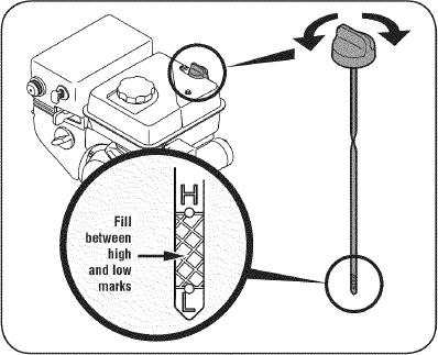
Figure 11
- Ajuste firmemente la varilla de medición antes de arrancar el motor.
Cambio de aceite del motor
NOTA: Cambie el aceite después de las 5 primeras horas de operación y después de cada 50 horas de operación o una vez por temporada.
- Vacíe el combustible del tanque haciendo funcionar el motor hasta que el tanque de combustible esté vacío. Cerciórese de que la tapa del combustible está asegurada.
- Coloque un recipiente adecuado para recolectar el aceite bajo el tapón de drenaje de aceite.
- Retire el tapón de drenaje de aceite. Vea la Figura 12.
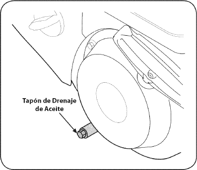
Figure 12
- Incline el motor para drenar el aceite en el recipiente. El aceite usado se debe descartar en un centro de recolección adecuado.
PRECAUCIÓNEl aceite usado es un residuo peligroso. Elimine el aceite usado adecuadamente. No lo arroje junto con los residuos domiciliarios. Consulte a las autoridades locales o al centro de servicio Sears para averiguar dónde hay instalaciones para la eliminación/ reciclaje segura(o) del aceite usado.
- Vuelva a colocar el tapón de drenaje de aceite y ajústelo bien.
- Rellene el motor con el petróleo recomendado. Ver la carta de Uso del Aceite Recomendada. La capacidad del aceite del motor es 20 onzas.
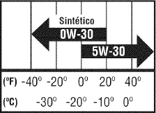
PRECAUCIÓNNO utilice aceites sin detergente o para motor de dos tiempos. Podría acortar la vida útil del motor.
- Vuelva a colocar y ajustar el tapón de llenado/la varilla de nivel de aceite.
PRECAUCIÓNLávese bien las manos con agua y jabón inmediatamente después de tocar aceite usado.
Control de la bujía
ADVERTENCIANO pruebe la chispa si no está la bujía de encendido. NO dé arranque al motor si no está la bujía de encendido.
ADVERTENCIASi el motor ha estado funcionando, el silenciador estará muy caliente. Tenga cuidado de no tocar el silenciador.
NOTA: Controle la bujía anualmente o cada 25 horas de operación. Cambie la bujía anualmente o cada 100 horas.
Para asegurarse de que el motor funcione bien, la bujía debe tener una separación correcta y no tener sedimentos.
- Retire la funda de la bujía y utilice una llave para bujías para extraerla. Vea la Figura 13.
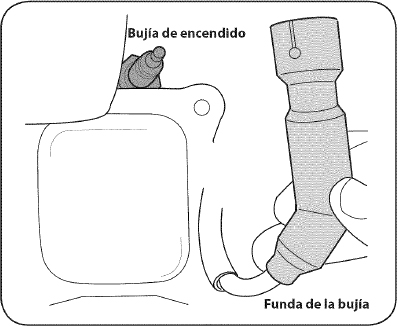
Figure 13
- Inspeccione visualmente la bujía. Descarte la bujía si presenta mucho desgaste, o si el aislante está agrietado o astillado. Limpie la bujía con un cepillo de alambre si la va a volver a utilizar.
- Mida la separación de bujía con un calibrador. Corrija de ser necesario torciendo el electrodo lateral. Vea la Figura 14. La separación debe establecerse entre 0,02 y 0,03 pulgadas (0,60-0,80 mm).
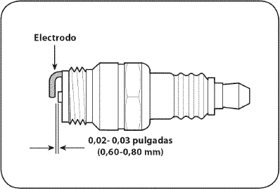
Figure 14
- Verifique que la arandela de la bujía esté en buenas condiciones y enrósquela manualmente para no estropear la rosca.
- Una vez que la bujía esté colocada, apriétela con una llave para comprimir la arandela.
NOTA: Cuando instale una bujía nueva, una vez colocada la bujía apriete 1/2 vuelta para comprimir la arandela. Cuando vuelva a colocar una bujía usada, una vez colocada la bujía apriete 1/8 -1/4 de vuelta para comprimir la arandela.
PRECAUCIÓNLa bujía debe estar bien ajustada. Una bujía floja puede recalentarse y dañar el motor.
LUBRICACIÓN
Eje de engranaje
El eje de engranaje (hexagonal) se debe lubricar al menos una vez por temporada o tras cada 25 horas de operación.
- Para prevenir el derramamiento, elimine todo el combustible del tanque haciendo funcionar el motor hasta que se detenga.
- Gire con cuidado la máquina quitanieve hacia arriba y hacia delante de manera que quede apoyada sobre la caja de la barrena.
- Retire la cubierta del marco inferior quitando los tornillos que la aseguran.
- Aplique al eje hexagonal una capa ligera de una grasa multiusos apta para condiciones climáticas múltiples. Vea la figura 15.
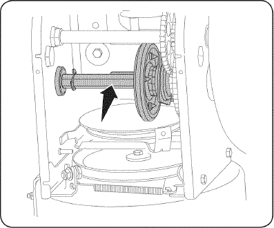
Figure 15
NOTA: Evite los derrames de aceite sobre la rueda de fricción de caucho y sobre la placa de transmisión de aluminio. Haciendo tan dificultará el sistema de paseo del lanzador de nieve. Borre cualquier exceso o petróleo derramado.
Ruedas
Retire ambas ruedas al menos una vez cada temporada. Limpie y recubra los ejes con una grasa para automotores multiusos antes de volver a instalar las ruedas.
Control direccional del canal
Lubrique el manguito del perno de ojo y la espiral con aceite 3-en-1 una vez por temporada.
Eje de la barrena
Al menos una vez por temporada, quite los pasadores de cuchilla del eje de la barrena. Rocíe lubricante al interior del eje, alrededor de los separadores. Asimismo, lubrique los cojinetes bridados que se encuentran en ambos extremos del eje. Vea la figura 16.
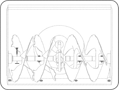
Figure 16
PLACA DE RASPADO Y ZAPATAS ANTIDESLIZANTES
La placa de raspado y las zapatas antideslizantes ubicadas en la base de la máquina quitanieve están sujetas a desgaste. Periódicamente debería controlar los pernos y reemplazarlos cuando sea necesario.
NOTA: Las zapatas de esta máquina tienen dos bordes de desgaste. Cuando un lado se desgasta, se las puede rotar 180° para usar el otro borde.
Para retirar las zapatas antideslizantes:
- Quite los cuatro pernos del carro, arandelas, y las tuercas de brida hexagonales que los aseguran a la máquina quitanieve.
- Monte las nuevas zapatas antideslizantes con cuatros pernos de carro (dos en cada lado), arandelas, y las tuercas de brida hexagonales. Consulte la figura 17.
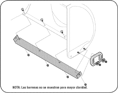
Figure 17
Para retirar la placa de raspado:
- Quite los pernos de carro y las tuercas hexagonales que la sujetan a la caja de la máquina quitanieve.
- Monte la placa de raspado nueva, asegurándose de que las cabezas de los pernos de carro se encuentren del lado interior de la caja. Ajuste bien.
AJUSTES
Cable de cambios
Si no se puede lograr toda la gama de velocidades (avance y retroceso), consulte la figura de la izquierda y ajuste el cable de cambios de la siguiente forma:
- Coloque la palanca de cambios en la tercera posición más rápida de avance.
- Afloje la tuerca hexagonal del soporte de posicionamiento del cable de cambios. Vea la figura 18.

Figure 18
- Gire el soporte hacia abajo para reducir el juego del cable.
- Vuelva a apretar la tuerca hexagonal.
Control de la transmisión
Cuando se suelta el control de la transmisión y está en posición desenganchada arriba, el cable debe tener muy poco juego. NO debe estar tenso. También, si hay excesivo flojo en el cable de paseo o si la unidad experimenta el paseo intermitente usando, el cable puede tener que ser ajustado.
Compruebe el ajuste del control de la transmisión de la siguiente forma:
- Cuando suelte el control de la transmisión, empuje suavemente la máquina quitanieve hacia delante. La unidad debería avanzar libremente.
- Enganche el control de la transmisión e intente empujar suavemente la máquina quitanieve hacia delante. Las ruedas no deben girar. La unidad no debe avanzar libremente.
- Con el control de la transmisión suelto, mueva la palanca de cambios hacia atrás y hacia delante entre la posición R2 y la posición F6 varias veces. No debería haber resistencia en la palanca de cambios.
- Si falla cualquiera de las pruebas anteriores, es necesario ajustar el cable de la transmisión. Proceda de la siguiente manera:
- Apague el motor como se indica en la sección de Operación.
- Afloje la tuerca hexagonal inferior del soporte del cable de la transmisión. Vea la figura 19.
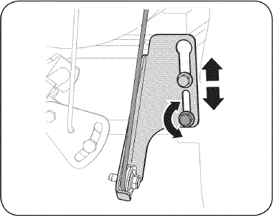
Figure 19
- Ubique la ménsula hacia arriba para brindar más juego (o hacia abajo para aumentar la tensión del cable).
- Vuelva a apretar la tuerca hexagonal superior.
Soporte del canal
Si la espiral situada en la parte inferior del control direccional del canal no se engancha completamente con el montaje del canal, es posible ajustar el soporte del canal. Para hacerlo:
- Afloje las dos tuercas que sujetan el soporte del canal y cambie su posición ligeramente. Vea la figura 20.
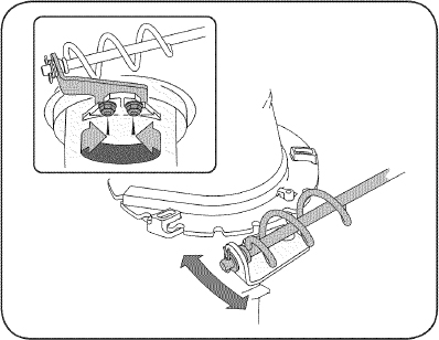
Figure 20
- Vuelva a ajustar las tuercas.
Control de la barrena
Consulte la secion de montaje para ajustar dicho control.
Zapatas antideslizantes
Consulte la secion de montaje para ajustar Las zapatas antideslizantes.
REEMPLAZO DE LA CORREA
La Correa de la barrena
Para retirar y reemplazar la correa de la barrena de su máquina quitanieve, proceda como se indica a continuación:
- Para prevenir el derramamiento, elimine todo el combustible del tanque haciendo funcionar el motor hasta que se detenga.
- Saque la cubierta plástica de la correa ubicada en el frente del motor. Para ello saque los dos tornillos autorroscantes. Vea la figura 21.
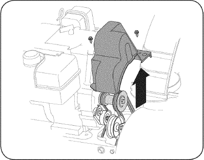
Figure 21
- Saque la correa de la barrena de la polea del motor. Vea la figura 22.
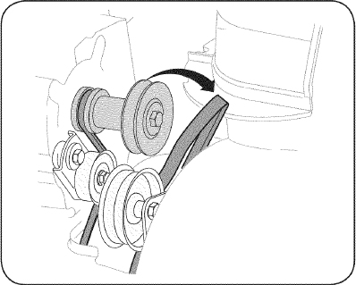
Figure 22
- Gire con cuidado la máquina quitanieve hacia arriba y hacia delante de manera que quede apoyada sobre la caja de la barrena.
- Saque la cubierta del marco desde debajo de la máquina quitanieve retirando los cuatro tornillos autorroscantes que la aseguran. Vea la figura 23.
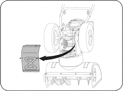
Figure 23
6.
- Afloje y retire el tornillo con reborde que actúa como guarda de la correa. Vea la figura 24.
- Desenganche el resorte de la ménsula de soporte del marco.
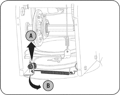
Figure 24
- Retire la correa de alrededor de la polea de la barrena y deslice la misma entre la ménsula de soporte y la polea de la barrena. Vea la figura 25.
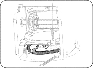
Figure 25
- Para realizar el reensamblado de la correa de la barrena siga las instrucciones en orden inverso.
- Realice la prueba de Control de Taladro perfilada en la sección de Asamblea de este manual.
NOTA: NO olvide volver a instalar el tornillo con reborde y volver a conectar el resorte al marco tras instalar una correa de la barrena de repuesto.
La correa de la transmisión
Para retirar y reemplazar la correa de la barrena de su máquina quitanieve, proceda como se indica a continuación:
- Para prevenir el derramamiento, elimine todo el combustible del tanque haciendo funcionar el motor hasta que se detenga.
- Saque la cubierta plástica de la correa ubicada en el frente del motor. Para ello saque los dos tornillos autorroscantes. Vea la figura 21.
- Saque la correa de la barrena de la polea del motor.
- Tome la polea loca y gírela hacia la derecha. Vea la figura 26.
- Levante la correa de la barrena para sacarla de la polea del motor.
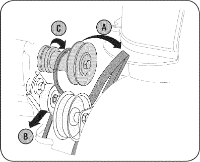
Figure 26
- Gire con cuidado la máquina quitanieve hacia arriba y hacia delante de manera que quede apoyada sobre la caja de la barrena.
- Saque la cubierta del marco desde debajo de la máquina quita nieve retirando los tornillos autorroscantes que la aseguran. Vea la figura 23.
- Detrás la parada se escapa para aumentar la autorización entre el disco de rueda de fricción y rueda de fricción. Vea la figura 27.
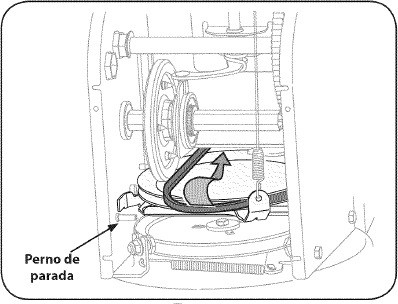
Figure 27
- Deslice la correa de la transmisión fuera de la polea y de entre la rueda de fricción y el disco de la rueda de fricción. Vea la figura 27
- Retire y reemplace la correa en el orden inverso. Asegúrese de volver a instalar el perno de parada.
EXTRACCIÓN DE LA RUEDA DE FRICCIÓN
Si la máquina quitanieve no se acciona cuando el control de la transmisión está engranado, y si al realizar el ajuste del cable de control de la transmisión que aparece el problema no se corrige, tal vez se deba reemplazar la rueda de fricción. Siga las instrucciones que aparecen a continuación. Examine la rueda de fricción en busca de signos de desgaste o grietas y reemplace si es necesario.
- Para prevenir el derramamiento, elimine todo el combustible del tanque haciendo funcionar el motor hasta que se detenga.
- Coloque la palanca de cambios en la tercera posición de avance (F3).
- Gire con cuidado la máquina quitanieve hacia arriba y hacia delante de manera que quede apoyada sobre la caja de la barrena.
- Saque la cubierta del marco desde debajo de la máquina quitanieve retirando los tornillos autorroscantes que la aseguran.
- Retire la rueda derecha quitando el tornillo y la arandela de campana que la aseguran al eje. Vea la figura 28.
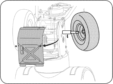
Figure 28
- Retire con cuidado la tuerca hexagonal y la arandela que sujetan el eje hexagonal al marco de la máquina quitanieve, y golpee suavemente el extremo del eje para desplazar el cojinete de bolas del lado derecho del marco. Vea la figura 29.
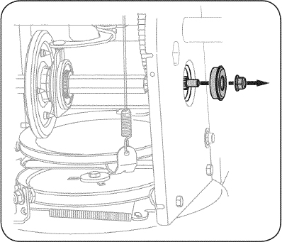
Figure 29
NOTA: Tenga cuidado de no dañar las roscas del eje.
- Con cuidado, ubique el eje hexagonal hacia abajo y hacia la izquierda antes de deslizar con precaución el montaje de la rueda de fricción fuera del eje. Vea la figura 30.
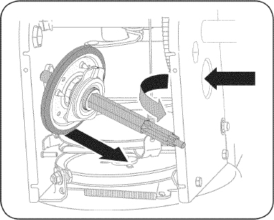
Figure 30
NOTA: Cuando se desea reemplazar el conjunto de la rueda de fricción completo, descarte la pieza desgastada y deslice la nueva pieza en el eje hexagonal.
- Para reensamblar los componentes siga los pasos anteriores en orden inverso.
- Realice la Prueba de Control de Paseo perfilada antes en la sección de Servicio y Mantenimiento.
Si está desmontando la rueda de fricción para reemplazar únicamente el anillo de goma, proceda como se indica a continuación:
- Saque los cuatro tornillos de mantienen unidas las placas laterales de la rueda de fricción. Vea la figura 31.
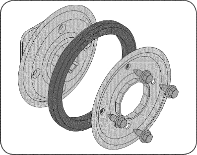
Figure 31
- Retire el anillo de goma de entre las placas.
- Reensamble las placas laterales con un nuevo anillo de goma.
NOTA: Al reensamblar el conjunto de la rueda de fricción, asegúrese de que el anillo de goma esta correctamente centrado y asentado entre las placas laterales. Apriete cada tornillo únicamente un giro antes de girar la rueda en el sentido de las agujas del reloj y proceder con el siguiente tornillo. Repita este proceso varias veces para asegurarse de que las placas se aprietan con la misma fuerza (entre 6 y 9 pies-libras).
- Vuelva a deslizar el conjunto de la rueda de fricción sobre el eje hexagonal y siga los pasos anteriores en orden inverso para reensamblar los componentes.
- Realice la Prueba de Control de Paseo perfilada antes en la sección de Servicio y Mantenimiento.
BARRENAS
Las barrenas están ajustadas al eje espiral con cuatro pasadores de cuchilla y pasadores de chaveta. Si la barrena golpea un objeto extraño o una barra de hielo, la máquina quitanieve está diseñada de manera que los pasadores se pueden cortar. Si las barrenas no giran, verifique si los pasadores se cortaron. Vea la figura 32.
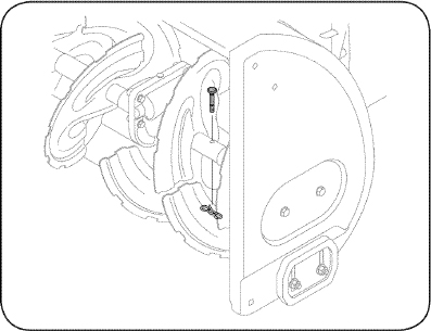
Figure 32
PRECAUCIÓNNUNCA cambie los pasadores de cuchilla de las barrenas por otra cosa que los pasadores de cuchilla de repuesto del fabricante del equipo original, Sears SKU# 88389/ N° de pieza 738-04124A. Cualquier daño que sufra el engranaje de la barrena o cualquier otro componente por dejar de hacerlo lo anterior, NO estará cubierto por la garantía de su máquina quitanieve.
ADVERTENCIASiempre debe apagar el motor de la máquina quitanieve y retirar la llave antes de cambiar los pasadores de cuchilla.
ALMACENAMIENTO FUERA DE TEMPORADA
Si no se va a utiliza el equipo durante 30 días o más, o si es el final de la temporada de nieve y ya no existe posibilidad de que nieve, es necesario almacenar el equipo de manera adecuada. Siga las instrucciones de almacenamiento que se indican a continuación para garantizar el rendimiento máximo de la máquina quitanieve durante muchos años.
PREPARACIÓN DEL MOTOR
Los motores que se almacenan durante más de 30 días necesitan ser drenados de combustible para evitar que se deterioren y se forme goma en el sistema de combustible o en las piezas principales del carburador. Si la gasolina de su motor se deteriora durante el almacenamiento, es posible que deba reparar o reemplazar el carburador y otros componentes del sistema de combustible.
- Elimine todo el combustible del tanque haciendo funcionar el motor hasta que se detenga. No intente de combustible para el motor.
- Cambie el aceite del motor.
- Extraiga la bujía de encendido y vierta en el cilindro aproximadamente 1 onza (30 mi) de aceite para motor limpio. Tire varias veces del arrancador de retroceso para distribuir el aceite y reinstale la bujía.
- Limpie los residuos de alrededor del motor, y debajo, alrededor, y detrás del silenciador. Aplique una capa delgada de aceite en todas las áreas que pueden llegar a oxidarse.
- Almacene en un sector limpio, seco y bien ventilado, lejos de cualquier artefacto que funcione con una llama o luz piloto como un horno, calentador de agua o secador de ropa. Evite cualquier sector con un motor eléctrico que produzca chispas o donde se utilicen herramientas eléctricas.
ADVERTENCIANunca almacene la máquina quitanieve con combustible en el tanque en un espacio cerrado o en áreas con poca ventilación, donde los gases del combustible puedan alcanzar el fuego, chispas o una luz piloto como la que tienen algunos hornos, calentadores de agua, secadores de ropa o algún otro dispositivo a gas.
- Si es posible, evite sectores de almacenamiento con mucha humedad.
- Mantenga el motor nivelado en el almacén. La inclinación del motor puede causar pérdidas de combustible o aceite.
PREPARACIÓN DE LA MÁQUINA QUITANIEVE
- Cuando almacene la máquina quitanieve en un galpón de depósito metálico o con poca ventilación, tenga especial cuidado de realizarle un tratamiento anti- oxidante al equipo. Use aceite ligero o silicón para recubrir el equipo, especialmente las cadenas, los resortes, los cojinetes y los cables.
- Elimine todo el polvo del exterior del motor y del equipo.
- Siga las recomendaciones de lubricación en la sección de mantenimiento de este manual.
- Almacene el equipo en un área despejada y seca.
SOLUCIÓN DE PROBLEMAS
| Problema | Causa | Remedio |
|---|---|---|
| El motor no arranca | 1. La palanca de obturación no está en la posición ON (encendido) 2. Se ha desconectado el cable de la bujía 3. La bujía no funciona correctamente 4. El tanque de combustible está vacío o el combustible es viejo 5. El motor no está cebado 6. La llave no se encuentra en el encendido del motor 7. Cable de extensión no conectado (cuando se usa el botón de arranque eléctrico, en los modelos equipados). |
1. Ponga el interruptor en la posición CHOKE (obturación). 2. Conecte el cable a la bujía. 3. Limpie, ajuste la distancia disruptiva o cambie. 4. Llene el tanque con gasolina limpia y fresca. 5. Cebe el motor tal y como se indica en la sección de operación. 6. Inserte la llave totalmente dentro del interruptor. 7. Conecte un extremo del cable de extensión a la salida de arranque eléctrico y el otro extremo a un triple de 120-voltios, de tierra, toma de CA. |
| El motor funciona de manera errática | 1. La unidad está funcionando en la posición CHOKE (obturación) 2. El combustible es viejo 3. Agua o suciedad en el sistema del combustible 4. Más gobernados motor |
1. Cambie la palanca de obturación a la posición OFF (apagado). 2. Llene el tanque con gasolina limpia y fresca. 3. Drenar el tanque de combustible en el motor en marcha hasta que se detenga. Vuelva a llenarlo con combustible limpio. 4. Contacte con su centro de partes y reparaciones Sears. |
¿NECESITA MÁS AYUDA?
Encontrará la respuesta y más en managemylife.com - ¡sin cargo!
En línea podrá encontrar este manual y los manuales de todos los otros productos que posea.
Sus preguntas serán respondidas por nuestro equipo de especialistas.
Obtenga un plan de mantenimiento personalizado para su hogar.
Encuentre información y herramientas que lo ayudarán con los proyectos de su hogar.

SOLUCIÓN DE PROBLEMAS
| Problema | Causa | Remedio |
|---|---|---|
| Demasiada vibración | 1. Hay piezas que están flojas o la barrena está dañada | 1. Detenga el motor de inmediato y desconecte el cable de la bujía. Ajuste todos los pernos y las tuercas. Si la vibración continúa, lleve la unidad a reparar a un centro de partes y reparación Sears. |
| Pérdida de potencia | 1. El cable de la bujía está flojo 2. El orificio de ventilación del tapón de llenado del combustible está obstruido |
1. Conecte y ajuste el cable de la bujía. 2. Retire el hielo y la nieve del tapón de llenado del combustible. Compruebe que el orificio de ventilación no esté obstruido. |
| La unidad no se autopropulsa | 1. El cable del control de transmisión necesita un ajuste 2. La correa de transmisión está floja o dañada 3. Rueda de fricción llevada puesta. |
1. Ajuste el cable del control de transmisión. Consulte la sección de Servicio y Mantenimiento. 2. Reemplace la correa de la transmisión. Consulte la sección de Servicio y Mantenimiento. 3. Rueda de fricción de cambio o contacte con su centro de partes y reparaciones Sears. |
| La unidad no descarga la nieve | 1. El montaje del canal está tapado 2. Hay un objeto extraño en la barrena 3. El cable del control de la barrena necesita un ajuste 4. La correa de la barrena está floja o dañada 5. El/los pasador/es de cuchilla están cortados |
1. Detenga el motor de inmediato y desconecte el cable de la bujía. Limpie el montaje del canal y el interior de la caja de la barrena con la herramienta de limpieza o una varilla. 2. Detenga el motor de inmediato y desconecte el cable de la bujía. Retire el objeto de la barrena con la herramienta de limpieza o una varilla. 3. Ajuste el cable del control de la barrena. Consulte la sección de montaje. 4. Reemplace la correa de la barrena Consulte la sección de Servicio y Mantenimiento. 5. Reemplace con nuevo(s) pasador(es) de cuchilla. |
| Chute no girar 180 grados | 1. Chute montados incorrectamente. | 1. Unassemble tolva de control y volver a como se indica en la Asamblea sección. |
¿NECESITA MÁS AYUDA?
Encontrará la respuesta y más en managemylife.com - ¡sin cargo!
En línea podrá encontrar este manual y los manuales de todos los otros productos que posea.
Sus preguntas serán respondidas por nuestro equipo de especialistas.
Obtenga un plan de mantenimiento personalizado para su hogar.
Encuentre Información y herramientas que lo ayudarán con los proyectos de su hogar.

MTD CONSUMER GROUP, INC. (MTD), el Bordo de Recursos de Aire de California (CARB) y la Agencia de Protección Medioambiental de Estados Unidos (U. S. EPA)
Declaración de Garantía del Sistema de Control de Emisiones
(Derechos y obligaciones del propietario según la garantía contra defectos)
LA COBERTURA DE SISTEMA DE CONTROL DE EMISIÓN ES APLICABLE A MOTORES CERTIFICADOS COMPRADOS EN CALIFORNIA EN 2005 Y A PARTIR DE ENTONCES, QUE SON USADOS EN CALIFORNIA, Y HASTA AÑO 2005 DE MODELO CERTIFICADO Y MOTORES POSTERIORES QUE SON COMPRADOS Y USADOS EN OTRA PARTE EN LOS ESTADOS UNIDOS.
California y en otra parte en la Cobertura de Garantía de Defectos de Control de Emisión de los Estados Unidos
El Bordo de Recursos de Aire de California (CARB), la U. S. EPA y MTD se complacen en explicar la garantía del sistema de control de emisiones de su motor para equipo todo terreno, modelo, año 2005 y versiones posteriores. En California, los nuevos motores pequeños para equipo todo terreno se deben diseñar, fabricar y equipar para cumplir con estándares de antiniebla tóxica de estados. En otra parte en los Estados Unidos, el nuevo no camino, motores de ignición de chispa certificados para el modelo 2005 y más tarde, debe encontrar el juego de estándares similar adelante por los Estados Unidos. EPA. MTD debe garantizar el sistema de control de emisiones de su motor por el período de tiempo indicado más abajo, siempre y cuando no haya existido uso incorrecto, negligencia ni mantenimiento inadecuado de su motor pequeño para equipo todo terreno.
El sistema de control de emisiones puede incluir piezas como, por ejemplo, el carburador, sistema de inyección de combustible, el sistema de encendido, el catalizador, los depósitos de combustible, abastece de combustible líneas, gorras de combustible, válvulas, latas, filtros, mangueras de vapor, abrazaderas, conectores y otros componentes relacionados con las emisiones.
Donde exista una condición cubierta por la garantía, MTD reparará su motor pequeño para equipo todo terreno sin costo alguno incluyendo el diagnóstico, las piezas y la mano de obra.
COBERTURA DE LA GARANTÍA DEL FABRICANTE:
Este sistema de control de emisiones se garantiza por el término de dos años. Si alguna pieza de su motor relacionada con las emisiones es defectuosa, MTD reparará o sustituirá dicha pieza.
RESPONSABILIDADES DEL PROPIETARIO SEGÚN LA GARANTÍA:
Como propietario de un motor pequeño de equipo todo terreno, usted es responsable de realizar el mantenimiento necesario que figura en el manual del propietario. MTD le recomienda que conserve todos los recibos que cubren los servicios de mantenimiento del motor pequeño para equipo todo terreno, no obstante lo cual MTD no podrá denegar el cumplimiento de la garantía únicamente por la falta de recibos o por su imposibilidad de asegurar que se realizarán todos los servicios de mantenimiento programado.
Como propietario del motor pequeño para equipo todo terreno, sin embargo, usted también debe saber que MTD puede denegar la cobertura de la garantía si su motor pequeño para equipo todo terreno o una pieza del mismo fallan debido a uso incorrecto, negligencia, mantenimiento indebido o a modificaciones no aprobadas.
Usted es responsable de presentar la cortadora de césped al centro de distribución o de mantenimiento de MTD CONSUMER GROUP, INC. tan pronto como apareciera el problema. Las reparaciones cubiertas por la garantía se deben llevar a cabo en un lapso razonable que no exceda de 30 días. Si desea realizar alguna consulta con respecto a la cobertura de la garantía, debe ponerse en contacto con su distribuidor local de MTD. Para comunicarse con la Línea de Asistencia al Cliente de Distribuidores de MTD, llame al número (877) 282-8684.
REQUERIMIENTOS DE GARANTÍA SOBRE DEFECTOS PARA MOTORES PEQUEÑOS DE EQUIPO TODO TERRENO DE 1995 Y VERSIONES POSTERIORES:
Esta sección se aplica a motores pequeños de equipo todo terreno de 1995 y versiones posteriores. El período de garantía comienza a partir de la fecha en que el motor o el equipo se entregan al comprador final.
(a) Cobertura de la garantía contra emisiones generales
MTD garantiza al comprador final y a cada comprador subsiguiente que el motor:
- ha sido diseñado, construido y equipado de manera que cumpla con todas las regulaciones vigentes adoptadas por el Departamento de los Recursos de Aire en virtud a su autoridad conferida en los capítulos 1 y 2, Parte 5, División 26 del Código de Salud y Seguridad; y
- está libre de defectos en los materiales y en la mano de obra que causen la falla de una pieza bajo garantía que sea idéntica en todos los aspectos materiales a la pieza como aparece descripta en la aplicación del fabricante del motor para certificación por un período de dos años.
(b) La garantía sobre piezas relacionadas con emisiones se interpretará de la siguiente manera:
- Cualquier pieza cubierta por garantía que no esté programada para su reemplazo según el mantenimiento requerido en las instrucciones escritas de la Subsección (c) debe estar garantizada por un período de garantía definido en la Subsección (a) (2). Si la pieza falla durante el período de cobertura de la garantía, la misma será reparada o reemplazada por MTD de acuerdo con la Subsección (4) a continuación. Cualquier pieza reparada o reemplazada según la garantía se garantizará por el resto del período de garantía.
- Cualquier pieza cubierta por garantía que esté programada solo para inspección regular en las instrucciones escritas de la Subsección (c) debe estar garantizada por un período de garantía definido en la Subsección (a) (2). Una declaración en dichas instrucciones por escrito al efecto de “reparación o reemplazo según sea necesario” no reducirá el período de cobertura de la garantía. Cualquier pieza reparada o reemplazada según la garantía se garantizará por el resto del período de garantía.
- Cualquier pieza garantizada que esté programada para reemplazo según el mantenimiento requerido de conformidad con las instrucciones escritas de la Subsección (c) se garantiza por el período de tiempo anterior a la primera fecha de reemplazo programada para esa pieza. Si la pieza falla antes del primer reemplazo programado, la misma será reparada o reemplazada por MTD de acuerdo con la Subsección (4) a continuación. Cualquier pieza reparada o reemplazada bajo garantía se garantizará por el resto del período anterior al primer reemplazo programado puntual para esa pieza.
- La reparación o el reemplazo de cualquier pieza garantizada de conformidad con las disposiciones de la garantía que aquí se estipula se debe realizar en un centro de garantía sin costo alguno para el propietario.
- Sin perjuicio de las disposiciones de la Subsección (4) anterior, los servicios o reparaciones cubiertos por la garantía deben ser suministrados por todos los centros de distribución de MTD que tengan la franquicia para realizar reparaciones y mantenimiento a los motores en cuestión.
- El propietario no debe afrontar ningún cargo para trabajos de diagnóstico que lleven a la conclusión de que una pieza bajo garantía presenta efectivamente defectos, siempre y cuando dicho diagnóstico sea llevado a cabo en un centro cubierto por la garantía.
- El fabricante del motor es responsable por daños causados a otros componentes de motores derivados de la falla bajo garantía de cualquier pieza garantizada.
- Durante todo el período de garantía del motor definido en la Subsección (a) (2), MTD mantendrá un suministro de piezas cubiertas por garantía suficiente para satisfacer la demanda esperada para tales piezas.
- Cualquier pieza de reemplazo se podrá usar para el cumplimiento del mantenimiento o reparaciones bajo garantía, y se suministrará sin cargo al propietario. Dicho uso no reducirá las obligaciones de garantía de MTD.
- No se podrán usar piezas adicionales ni modificadas que no estén exentas de acuerdo con el Departamento de los Recursos del Aire (Air Resources Board). El uso de piezas adicionales o modificadas no exentas será causa suficiente para anular un reclamo bajo garantía realizado de acuerdo con este artículo. El fabricante del motor no tendrá responsabilidad, en conformidad con este artículo, de garantizar fallas de piezas garantizadas que fueren causadas por el uso de una pieza no exenta adicional o modificada.
(c) MTD incluirá una copia de la siguiente lista de piezas bajo garantía contra emisiones con cada nuevo motor, utilizando las partes de la lista aplicables al motor.
- Sistema de medición de combustible
- Sistema de mejora para inicio en frío (cebado suave)
- Carburador y componentes internos
- Bomba de combustible
- Depósito de combustible
- Sistema de inducción de aire
- Filtro de aire
- Colector de entrada
- Sistema de encendido
- Bujía(s)
- Sistema de encendido por magneto
- Sistema de escape
- Catalizador
- SAI (válvula de Caña)
- Componentes varios utilizados en el sistema anterior
- Válvulas e interruptores de vacío, temperatura, posición sensibles al tiempo
- Conectores y montajes
- Control de Evaporative
- Manguera de Combustible certificada para ARB evaporative emisión de 2006.
- Abrazaderas de Manguera de Combustible
- Gorra de combustible atada
- Lata de carbón
- Líneas de vapor
GDOC-100174 Rev.B
Busque el período de duración de emisiones importantes yla información de clasificación de aire en la etiqueta de emisiones de su motor
Los motores cuyo cumplimiento con los estándares de emisión Tier 2 de la Comisión de Recursos Ambientales de California (CARB) esté certificado deben exhibir la información relacionada con el período de duración de las emisiones y la clasificación de aire. Sears Brands Management Corporation ponen esta información a disposición del consumidor en nuestras etiquetas de emisiones.
El Período de Duración de las Emisiones describe el número de horas de tiempo real de funcionamiento para el cual se certifica que el motor cumple con las reglas de emisión, descontando el mantenimiento adecuado del mismo según las instrucciones de operación y mantenimiento. Se utilizan las siguientes categorías:
Moderado: Se certifica que el motor cumple con las reglas de emisión durante 125 horas de tiempo real de funcionamiento del motor.
Inmediato: Se certifica que el motor cumple con las reglas de emisión durante 250 horas de tiempo real de funcionamiento del motor.
Extendido: Se certifica que el motor cumple con las reglas de emisión durante 500 horas de tiempo real de funcionamiento del motor.
Por ejemplo, una cortadora de césped típica que se empuja desde atrás se usa entre 20 y 25 horas por año. Por lo tanto, el Período de Duración de Emisiones de un motor con una clasificación intermedia sería equivalente a entre 10 y 12 años.
La clasificación de aire es un número calculado para describir el nivel relativo de emisiones para un grupo de motores en particular. Cuanto menor sea la clasificación de aire, mayor es la limpieza del motor. La información se presenta de forma gráfica en la etiqueta de emisiones.
Después del 1 de julio de 2000, busque el período de cumplimiento de las reglas de emisiones en la etiqueta de cumplimiento de las reglas de emisiones del motor
Después del 1 de julio de 2000 se certificará que determinados motores Sears Brands Management Corporation cumplen con los estándares de emisiones de la fase 2 de la Agencia de Protección Ambiental de los Estados Unidos (USEPA). Para los motores certificados para la etapa 2, el período de cumplimiento con las reglas de emisiones al cual se hace referencia en la etiqueta de cumplimiento con las reglas de emisiones indica el número de horas de funcionamiento para el cual se ha demostrado que el motor cumple con los requerimientos federales de emisión.
Para los motores con desplazamiento inferior a 225 cc, Categoría C = 125 horas, B = 250 horas y A = 500 horas.
Para los motores con desplazamiento de 225 cc o más, Categoría C = 250 horas, B = 500 horas y A = 1000 horas.
El desplazamiento de los motores de la serie modelo 150112 es 249 cc.
La presente es una representación genérica de la etiqueta de emisión que se encuentra generalmente en un motor certificado.
GDOC-100182 Rev.A
ACUERDO DE PROTECCIÓN PARA REPARACIONES
Felicitaciones por haber realizado una adquisición inteligente. El producto Craftsman® que ha adquirido está diseñado y fabricado para brindar muchos años de funcionamiento confiable. Pero como todos los productos a veces puede requerir de reparaciones. Es en ese momento cuando el disponer de un Acuerdo de protección para reparaciones le puede ahorrar dinero y problemas.
A continuación se detallan los puntos incluidos en el Acuerdo:
|
Servicio experto prestado por nuestros 10,000 especialistas en reparaciones profesionales |
|---|---|
|
Servicio ilimitado sin cargo para las piezas y la mano de obra en todas las reparaciones cubiertas |
|
Reemplazo del producto hasta 1500 dólares si no es posible reparar el producto cubierto |
|
Descuento de 25% del precio normal del servicio y de las piezas relacionadas con el mismo que no estén cubiertas por el acuerdo; además, 25% del precio normal de la verificación de mantenimiento preventivo |
|
Ayuda rápida por teléfono - lo llamamos Resolución Rápida - el apoyo telefónico de un Chamusca al representante. Piense en nosotros como el manual “de un dueño hablador.” |
Una vez adquirido el Acuerdo, puede programar el servicio con tan sólo realizar una llamada telefónica. Puede llamar en cualquier momento del día o de la noche o programar un servicio en línea.
El Acuerdo de Protección de Reparación es una compra sin riesgo. Si usted anula por alguna razón durante el período de garantía de producto, proporcionaremos un reembolso lleno. O, un reembolso prorrateado en cualquier momento después del período de garantía de producto expira. ¡Adquiera hoy su acuerdo de protección para reparaciones!
Se aplican determinadas limitaciones y exclusiones. Para obtener información adicional y precios en los Estados Unidos llame al 1-800-827-6655.
El *Coverage en Canadá varía en algunos artículos. Para detalles llenos la llamada Chamusca Canadá en 1-800-361-6665.
Servicio de instalación de Sears
Si desea solicitar la instalación profesional de Sears de aparatos domésticos, dispositivos para abrir portones, calentadores de agua y otros artículos domésticos importantes, en los Estados Unidos o Canadá llame al 1-800-4-MY-HOME®.
Número de servicio


Parts & More
Downdraft Ventilation System
Front-Engine Lawn Tractor
Gas Snowblower
Heating & Cooling Combined Unit
Humidifier
Rear-Engine Riding Mower
Riding Mowers & Tractors
Side-By-Side Refrigerator
Television