- Kenmore refrigerator water filters
- Whirlpool refrigerator water filters
- Samsung refrigerator water filters
- GE refrigerator water filters
- LG refrigerator water filters
- Frigidaire refrigerator water filters
- KitchenAid refrigerator water filters
- Maytag refrigerator water filters
- Kenmore Elite refrigerator water filters
- Estate refrigerator water filters
- GE Profile refrigerator water filters
- Amana refrigerator water filters
- Bosch refrigerator water filters
- Dacor refrigerator water filters
- Electrolux refrigerator water filters
Top DIY repair help
View All Repair Categories
Appliances
Lawn & Garden
Power Tools
Home Improvement
Sports & Leisure
Heating & Cooling
Craftsman 113299142 table saw manual
Are you looking for information on using the Craftsman 113299142 table saw? This user manual contains important warranty, safety, and product feature information. View the user manual below for more details. Want a copy for yourself? Download or print a free copy of the user manual below.
TABLE SAW (OWNERS)(viewing)Download PDF
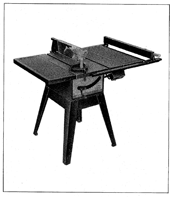

10-INCH TABLE SAW
- assembly
- operating
- repair parts
Sears
owners manual
MODEL NO. 113.299142
SAW ONLY
113.299040
SAW WITH LEGS TWO TABLE EXTENSIONS AND MOTOR
113.298470
SAW WITH LEGS ONE TABLE EXTENSION AND MOTOR
Serial Number __________________
Model and serial number may be found at the left-hand side of the base.
You should record both model and serial number in a safe place for future use.
CAUTION:
Read GENERAL and ADDITIONAL SAFETY INSTRUCTIONS carefully
Sold by SEARS, ROEBUCK AND CO., Chicago, IL. 60684 U.S.A.
Part No. 62588 Printed in U.S.A.
FULL ONE YEAR WARRANTY ON CRAFTSMAN TABLE SAWS
If within one year from the date of purchase, this Craftsman Table Saw fails due to a defect in material or workmanship, Sears will repair, it, free of charge.
Warranty service is available by simply contacting the nearest Sears store or Service Center throughout the United States.
This warranty gives you specific legal rights, and you may also have other rights which vary from state to state.
SEARS, ROEBUCK AND CO.
BSC 41-3
SEARS TOWER
CHICAGO, IL 60684
GENERAL SAFETY INSTRUCTIONS FOR POWER TOOLS
KNOW YOUR POWER TOOL
Read the owner’s manual carefully. Learn its application and limitations as well as the specific potential hazards peculiar to this tool.
GROUND ALL TOOLS
This tool is equipped with an approved 3-conductor cord and a 3-prong grounding type plug to fit the proper grounding type receptacle. The green conductor in the cord is the grounding wire. Never connect the green wire to a live terminal.
KEEP GUARDS IN PLACE
in working order, and in proper adjustment and alignment.
REMOVE ADJUSTING KEYS AND WRENCHES
Form habit of checking to see that keys and adjusting wrenches are removed from tool before turning it on.
KEEP WORK AREA CLEAN
Cluttered areas and benches invite accidents. Floor must not be slippery due to wax or sawdust.
AVOID DANGEROUS ENVIRONMENT
Don’t use power tools in damp or wet locations or expose them to rain. Keep work area well lighted. Provide adequate surrounding work space.
KEEP CHILDREN AWAY
All visitors should be kept a safe distance from work area.
MAKE WORKSHOP KID-PROOF
– with padlocks, master switches, or by removing starter keys.
DON’T FORCE TOOL
It will do the job better and safer at the rate for which it was designed.
USE RIGHT TOOL
Don’t force tool or attachment to do a job it was not designed for.
WEAR PROPER APPAREL
Do not wear loose clothing, gloves, neckties or jewelry (rings, wrist watches) to get caught in moving parts. Nonslip footwear is recommended. Wear protective hair covering to contain long hair. Roll long sleeves above the elbow.
USE SAFETY GOGGLES (Head Protection)
Wear Safety goggles (must comply with ANS Z87.1) at all times. Also, use face or dust mask if cutting operation is dusty, and ear protectors (plugs or muffs) during extended periods of operation.
SECURE WORK
Use clamps or a vise to hold work when practical. It’s safer than using your hand, frees both hands to operate tool.
DON’T OVERREACH
Keep proper footing and balance at all times.
MAINTAIN TOOLS WITH CARE
Keep tools sharp and clean for best and safest performance. Follow instructions for lubricating and changing accessories.
DISCONNECT TOOLS
before servicing; when changing accessories such as blades, bits, cutters, etc.
AVOID ACCIDENTAL STARTING
Make sure switch is in “OFF” position before plugging in.
USE RECOMMENDED ACCESSORIES
Consult the owner’s manual for recommended accessories. Follow the instructions that accompany the accessories. The use of improper accessories may cause hazards.
NEVER STAND ON TOOL
Serious injury could occur if the tool is tipped or if the cutting tool is accidentally contacted.
Do not store materials above or near the tool such that it is necessary to stand on the tool to reach them.
CHECK DAMAGED PARTS
Before further use of the tool, a guard or other part that is damaged should be carefully checked to ensure that it will operate properly and perform its intended function. Check for alignment of moving parts, binding of moving parts, breakage of parts, mounting, and any other conditions that may affect its operation. A guard or other part that is damaged should be properly repaired or replaced.
DIRECTION OF FEED
Feed work into a blade or cutter against the direction of rotation of the blade or cutter only.
NEVER LEAVE TOOL RUNNING UNATTENDED
Turn power off. Don’t leave tool until it comes to a complete stop.
ADDITIONAL SAFETY INSTRUCTIONS FOR TABLE SAWS
WARNING: FOR YOUR OWN SAFETY, DO NOT OPERATE YOUR SAW UNTIL IT IS COMPLETELY ASSEMBLED AND INSTALLED ACCORDING TO THE INSTRUCTIONS … AND UNTIL YOU HAVE READ AND UNDERSTOOD THE FOLLOWING.
GENERAL SAFETY INSTRUCTIONS FOR POWER TOOLS … SEE PAGE 2
GETTING TO KNOW YOUR SAW … SEE PAGE 20
BASIC SAW OPERATION … SEE PAGE 23
ADJUSTMENTS… SEE PAGE 29
MAINTENANCE … SEE PAGE 32
STABILITY OF SAW
If there is any tendency for the saw to tip over or move during certain cutting operations such as cutting extremely large heavy panels or long heavy boards, the saw should be bolted down.
If you attach any kind of table extensions over 24 in. wide, make sure they are supported underneath by a sturdy brace attached to saw base or bench.
LOCATION
The saw should be positioned so neither the operator nor a casual observer is forced to stand in line with the saw blade.
KICKBACKS
Kickbacks can cause serious injury: A “Kickback” occurs when a part of the workpiece binds between the sawblade and the rip fence or other fixed object, rises from the table, and is thrown toward the operator. Keep your face and body to one side of the sawblade, out of line with a possible “Kickback.” Kickbacks – and possible injury from them – can usually be avoided by:
- Maintaining the rip fence parallel to the sawblade.
- Keeping the sawblade sharp. Replacing anti-kickback pawls when points become dull.
- Keepings sawblade guard, spreader, and anti-kickback pawls in place and operating properly. The spreader must be in alignment with the sawblade and the pawls must stop a kickback once it has started. Check their action before ripping.
- NOT ripping work that is twisted or warped or does not have a straight edge to guide along the rip fence.
- NOT releasing work until you have pushed it all the way past the sawblade.
- Using a push stick for ripping widths of 2 to 6 in., and an auxiliary fence and push block for ripping widths narrower than 2 in. (See “Basic Saw Operation Using The Rip Fence” section.)
- NOT confining the cut-off piece when ripping or cross-cutting.
- When ripping apply the feed force to the section of the workpiece between the saw blade and the rip fence.
PROTECTION: EYES, HANDS, FACE, EARS, BODY
If any part of your saw is malfunctioning, has been damaged or broken … such as the motor switch, or other operating control, a safety device or the power cord … cease operating immediately until the particular part is properly repaired or replaced.
Wear safety goggles that comply with ANS Z87.1-1968, and a face shield if operation is dust. Wear ear plugs or muffs during extended periods of operation.
Small loose pieces of wood or other objects that contact the rear of the revolving blade can be thrown back at the operator at excessive speed. This can usually be avoided by keeping the guard and spreader in place for all thru-sawing operations (sawing entirely thru the work) AND by removing all loose pieces from the table with a long stick of wood IMMEDIATELY after they are cut off.
Use extra caution when the guard assembly is removed for resawing, dadoing, rabbeting, or molding – replace the guard as soon as that operation is completed.
NEVER turn the saw “ON” before clearing the table of all tools, wood scraps, etc., except the workpiece and related feed or support devices for the operation planned.
NEVER place your face or body in line with the cutting tool.
NEVER place your fingers or hands in the path of the sawblade or other cutting tool.
NEVER reach in back of the cutting tool with either hand to hold down or support the workpiece, remove wood scraps, or for any other reason. Avoid awkward operations and hand positions where a sudden slip could cause fingers or hand to move into a sawblade or other cutting tool.
DO NOT perform layout, assembly, or setup work on the table while the cutting tool is rotating.
DO NOT perform any operation “FREEHAND” – always use either the rip fence or the miter gauge to position and guide the work.
NEVER use the rip fence when crosscutting or the miter guage when ripping. DO NOT use the rip fence as a length stop.
Never hold onto or touch the “free end” of the workpiece or a “free piece” that is cut off, while power is “ON” and/or the sawblade is rotating.
Shut “OFF” the saw and disconnect the power cord when removing the table insert, changing the cutting tool, removing or replacing the blade guard, or making adjustments.
Provide adequate support to the rear and sides of the saw table for Wider or long workpieces.
Plastic and composition (like hardboard) materials may be cut on your saw. However, since these are usually quite hard and slippery, the anti-kickback pawls may not stop a kickback.
Therefore, be especially attentive to following proper set-up and cutting procedures for ripping. Do not stand, or permit anyone else to stand, in line with a potential kickback.
If you stall or jam the sawblade in the workpiece, turn saw “OFF”, remove the workpiece from the sawblade, and check to see if the sawblade is parallel to the table slots or grooves and if the spreader is in proper alignment with the sawblade. If ripping at the time, check to see if the rip fence is parallel with the sawblade. Readjust as indicated.
KNOW YOUR CUTTING TOOLS
Dull, gummy, or improperly sharpened or set cutting tools can cause material to stick, jam, stall the saw, or kickback at the operator.
Minimize potential injury by proper cutting tool and machine maintenance.
NEVER ATTEMPT TO FREE A STALLED SAWBLADE WITHOUT FIRST TURNING THE SAW OFF.
Never use grinding wheels, abrasive cut-off wheels, friction wheels (metal slitting blades) wire wheels or buffing wheels.
USE ONLY ACCESSORIES DESIGNED FOR THIS SAW.
Cross-cutting operations are more conveniently worked and with greater safety if an auxiliary wood facing is attached to the miter gauge using the holes provided.
Make sure the top of the arbor or cutting tool rotates toward you when standing in normal operating position. Also make sure the cutting tool, arbor collars and arbor nut are installed properly. Keep the cutting tool as low as possible for the operation being performed. Keep all guards in place whenever possible.
Do not use any blade or other cutting tool marked for an operating speed less than 3450 RPM. Never use a cutting tool larger in diameter than the diameter for which the saw was designed. For greatest safety and efficiency when ripping, use the maximum diameter blade for which the saw is designed, since under these conditions the spreader is nearest the blade.
Adjust table inserts flush with the table top. NEVER operate the saw unless the proper insert is installed.
THINK SAFETY.
Safety is a combination of operator common sense and alertness at all times when the saw is being used.
NOTE AND FOLLOW SAFETY INSTRUCTIONS THAT APPEAR ON THE FRONT OF YOUR SAW.
DANGER
FOR YOUR OWN SAFETY READ AND UNDERSTAND OWNER’S MANUAL BEFORE OPERATING MACHINE:
- WEAR SAFETY GOGGLES
- USE SAW-BLADE GUARD FOR “THRU-SAWING”
- KEEP HANDS OUT OF PATH OF SAWBLADE
- USE A “PUSH-STICK” WHEN REQUIRED
- KNOW HOW TO AVOID “KICKBACKS”
- DO NOT PERFORM OPERATIONS “FREEHAND”
- WARNING: DO NOT ALLOW FAMILIARITY (GAINED FROM FREQUENT USE OF YOUR SAW) TO BECOME COMMONPLACE. - ALWAYS REMEMBER THAT A CARELESS FRACTION OF A SECOND IS SUFFICIENT TO INFLICT SEVERE INJURY.
- WARNING: THE 2-1/2” SAW PULLEY AND THE 2-1/2” MOTOR PULLEY FURNISHED, WILL RUN THE BLADE AT APPROXIMATELY 3450 RPM WHEN USED WITH A 3450 RPM MOTOR. NEVER SUBSTITUTE THESE PULLEYS TO INCREASE THIS SPEED BECAUSE IT COULD BE DANGEROUS.

The operation of any power tool can result in foreign objects being thrown into the eyes, which can result in severe eye damage. Always wear safety goggles complying with ANSI Z87.1 (shown on Package) before commencing power tool operation. Safety Goggles are available at Sears retail or catalog stores.
MOTOR SPECIFICATIONS AND ELECTRICAL REQUIREMENTS
This saw is designed to use a 3450 RPM motor only. Do not use any motor that runs faster than 3450 RPM. It is wired for operation on 110-120 volts, 60 Hz., alternating current. IT MUST NOT BE CONVERTED TO OPERATE ON 230 VOLTS. EVEN THOUGH SOME OF THE RECOMMENDED MOTORS ARE DUAL VOLTAGE.
The outlet in the switch box will accept either a 15 amp. or a 20 amp. motor plug.
RECOMMENDED CRAFTSMAN MOTORS FOR USE ON THIS SAW.
| H.P. | R.P.M. | Volts | Catalog No. |
|---|---|---|---|
| 1 | 3450 | 110-120 | 1217 |
| 1 | 3450 | 110-120 | 1220 |
See recommendation on saw for use in Canada
CAUTION: Do not use blower or washing machine motors or any motor with an automatic reset overload protector as their use may be hazardous.
CONNECTING TO POWER SOURCE OUTLET
This saw must be grounded while in use to protect the operator from electrical shock.
If power cord is worn or cut, or damaged in any way, have it replaced immediately.
If your saw is for use on less than 150 volts it has a plug that looks like below.
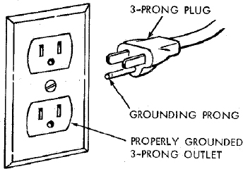
Plug power cord into 110-120V properly grounded type outlet protected by a 15-amp. time delay or Circuit-Saver fuse or circuit breaker.
IF YOU ARE NOT SURE THAT YOUR OUTLET IS PROPERLY GROUNDED, HAVE IT CHECKED BY A QUALIFIED ELECTRICIAN.
WARNING: DO NOT PERMIT FINGERS TO TOUCH THE TERMINALS OF PLUG WHEN INSTALLING OR REMOVING THE PLUG TO OR FROM THE OUTLET.
WARNING: IF NOT PROPERLY GROUNDED THIS POWER TOOL CAN INCUR THE POTENTIAL HAZARD OF ELECTRICAL SHOCK, PARTICULARLY WHEN USED IN DAMP LOCATIONS, IN PROXIMITY TO PLUMBING, OR OUT OF DOORS. IF AN ELECTRICAL SHOCK OCCURS THERE IS THE POTENTIAL OF A SECONDARY HAZARD SUCH AS YOUR HANDS CONTACTING THE SAWBLADE.
This saw is equipped with a 3-conductor cord and grounding type plug which has a grounding prong, approved by Underwriters’ Laboratories and the Canadian Standards Association. The ground conductor has a green lug and is attached to the tool housing at one end and to the ground prong in the attachment plug at the other end.
This plug requires a mating 3-conductor grounded type outlet as shown.
If the outlet you are planning to use for this saw is of the two prong type DO NOT REMOVE OR ALTER THE GROUNDING PRONG IN ANY MANNER. Use an adapter as shown and always connect the grounding lug to a known ground.
It is recommended that you have a qualified electrician replace the TWO prong outlet with a properly grounded THREE prong outlet.
An adapter as shown below is available for connecting plugs to 2-prong receptacles. The green grounding lug extending from the adapter must be connected to a permanent ground such as to a properly grounded outlet box.
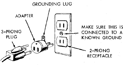
NOTE: The adapter illustrated is for use only if you already have a properly grounded 2-prong receptacle. Adapter is not allowed in Canada by the Canadian Electrical Code.
The use of any extension cord will cause some loss of power. To keep this to a minimum and to prevent over-heating and motor burn-out, use the table below to determine the minimum wire size (A.W.G.) extension cord. Use only 3 wire extension cords which have 3 prong grounding type plugs and 3-pole receptacles which will accept the plug on the saw.
| 1 H.P. MOTOR 110-120V | ||
|---|---|---|
| Extension Cord Length | Wire Size A.W.G. | |
| Up to 50 Ft. | ................ | 14 |
| 50 to 100 Ft. | ............... | 12 |
| 100 - 200 Ft. | ................ | 10 |
| 200 - 400 Ft. | ............... | 8 |
CHECK MOTOR ROTATION
WARNING: FOR YOUR OWN SAFETY, MAKE SURE PLUG IS NOT CONNECTED TO POWER SOURCE OUTLET. WHEN CHANGING MOTOR ROTATION.
The motor must rotate CLOCKWISE when viewed from the shaft end to which you will mount the pulley. (See page 16.) If it does not, change the direction according to the instructions furnished with the motor.
CONTENTS
- WARRANTY
- GENERAL SAFETY INSTRUCTIONS FOR POWER TOOLS
- ADDITIONAL SAFETY INSTRUCTIONS FOR TABLE SAWS
- MOTOR SPECIFICATIONS AND ELECTRICAL REQUIREMENTS
- UNPACKING AND CHECKING CONTENTS
- ASSEMBLY
- Installing Tilt Crank
- Checking Table Insert
- Checking Blade Squareness to Table
- Assembling Steel Legs
- Mounting Saw
- Attaching Table Extensions
- Installing Rip Fence Guide Bars
- Aligning Rip Fence
- Adjusting Rip Scale Pointer
- Repositioning Rip Fence Guide Bars
- Installing Blade Guard
- Mounting the Motor
- Installing Belt Guard
- Plugging in Motor
- GETTING TO KNOW YOUR SAW
- BASIC SAW OPERATION USING THE MITER GAUGE
- BASIC SAW OPERATION USING THE RIP FENCE
- ADJUSTMENTS
- MAINTENANCE
- LUBRICATION
- RECOMMENDED ACCESSORIES
- TROUBLE SHOOTING
- REPAIR PARTS
UNPACKING AND CHECKING CONTENTS
TOOLS NEEDED
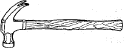
Hammer
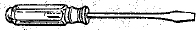
Medium Screwdriver Small Screwdriver
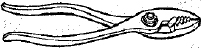
Pliers
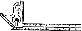
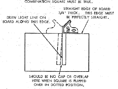
Combination Square

Wrenches
3/8 in.
1/2 in.
3/4 in.
7/16 in.
9/16 in.
Model 113.299142 Table Saw is shipped complete in one carton but DOES NOT INCLUDE Table Extension, Steel Legs, or motor.
Model 113.299040 Table Saw is shipped complete in one carton but INCLUDES Two Table Extensions, Steel Legs, and Motor.
Model 113.298470 Table Saw is shipped complete in one carton but INCLUDES One Table Extension, Steel Legs, and Motor.
Separate all parts from packing materials and check each one with the illustration and the list of Loose Parts to make certain all items are accounted for, before discarding any packing material.
If any parts are missing, do not attempt to assemble the table saw, plug in the power cord or turn the switch on until the missing parts are obtained and are installed correctly.
Remove the protective oil that is applied to the table top and edges of the table. Use any ordinary household type grease and spot remover.
CAUTION: Never use gasoline, naptha or similar highly volatile solvents.
Apply a coat of automobile wax to the table.
Wipe all parts thoroughly with a clean, dry cloth.
WARNING: FOR YOUR OWN SAFETY, NEVER CONNECT PLUG TO POWER SOURCE OUTLET UNTIL ALL ASSEMBLY STEPS ARE COMPLETE, AND YOU HAVE READ AND UNDERSTAND THE SAFETY AND OPERATIONAL INSTRUCTIONS.
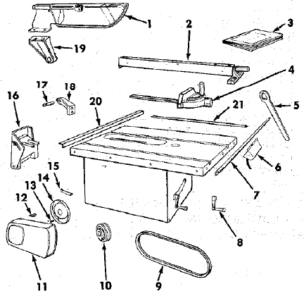
LIST OF LOOSE PARTS
| Key No. | Part Name | Qty. |
|---|---|---|
| 1 | Blade Guard and Spreader | 1 |
| 2 | Rip Fence | 1 |
| 3 | Owners Manual | 1 |
| 4 | Miter Gauge | 1 |
| 5 | Arbor Nut Wrench | 1 |
| 6 | Switch | 1 |
| 7 | Rip Fence Guide Bar with Rip Scala (Front) | 1 |
| 8 | Crank | 1 |
| 9 | V-Belt 1/2 in. × 41 in. | 1 |
| 10 | Pulley, 2-1/2 in, dia., with 5/8 in.bore | 1 |
| 11 | Belt and Pulley Guard | 1 |
| 12 | Belt Guard Clip | 3 |
| 13 | Self-Threading Screw, 10-32 × 1/2 in.long | 2 |
| 14 | Belt Guard Support | 1 |
| 15 | Belt Guard Support Bracket | 1 |
| 16 | Motor Base | 1 |
| 17 | Spreader Rod | 1 |
| 18 | Blade Guard Support with Screw | 1 |
| 19 | Spreader Support | 1 |
| 20 | Rip Fence Guide Bar (Rear) | 1 |
| 21 | Rip Fence Guide Bar Rod | 1 |
| Pkg. of Miscellaneous Small Parts No. 62586 | ||
| Consisting of the Following: | ||
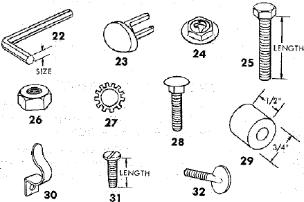
| 22 | Setscrew Wrench, 3/32 in. | 1 |
| 22 | Setscrew Wrench, 1/8 in. | 1 |
| 22 | Setscrew Wrench, 5/32 in. | 1 |
| Key No. | Part Name | Qty. |
|---|---|---|
| 23 | Switch Key | 2 |
| 24 | Self-Threading Nut | 2 |
| 25 | Hex Head Screw, 5/16 in.–18 × 1-1/2 in.long | 2 |
| 25 | Hex Head Screw, 5/16 in.–18 × 5/8 in.long | 3 |
| 25 | Hex Head Screw, 5/16 in.–18 × 1 in.long | 4 |
| 25 | Hex Head Screw, 1/4 in.–20 × 5/8 in.long | 2 |
| 26 | Hex Nut, 5/16 in.–18 (approx. dia. of hole 5/16 in.) | 8 |
| 26 | Hex Nut, 1/4 in.–20 (approx. dia. of hole 1/4 in.) | 2 |
| 27 | Lockwasher, 5/16 in. External Type (approx. dia. of hole 5/16 in.) | 10 |
| 27 | Lockwasher, 1/4 in. External Type (approx. dia. of hole 1/4 in.) | 2 |
| 28 | Carriage Bolt, 5/16 in.–18 × 3/4 in.long | 4 |
| 29 | Rip Fence Guide Bar Spacer | 2 |
| 30 | Cord Clamp | 2 |
| 31 | Pan Head Sheet Metal Screws, 3/8 in.long | 2 |
| 32 | Thumbscrew, 5/16 in.–18 × 1 in. long | 1 |
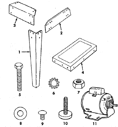
The following parts are included with Model 113.299040 and 113.298470
| 1 | Leg | 4 |
|---|---|---|
| 2 | Side Stiffener | 2 |
| 3 | End Stiffener | 2 |
| 4 | Table Extension (113.299040) | 2 |
| Table Extension (113.298470) | 1 | |
| Pkg. of Miscellaneous Small Parts, No. 82591 | ||
| Consisting of the Following: | ||
| 5 | Hex Head Screw 5/16 in-18 × 1-1/4 in. long | 12 |
| 6 | Lockwasher, 1/4 in. External Type (approx. dia. of hole 1/4 in.) | 24 |
| 6 | Lockwasher, 5/16 in. External Type (approx. dia. of hole 5/16 in.) | 12 |
| Key No. | Part Name | Qty. |
|---|---|---|
| 7 | Hex Nut, 1/4 in. – 20 (approx. dia. of hole 1/4 in.) | 24 |
| 7 | Hex Nut, 5/16 in. – 18 (approx. dia. of hole 5/16 in.) | 12 |
| 7 | Hex Nut, 1/2 in. – 13 (approx. dia. of hole 1/2 in.) | 8 |
| 8 | Flat Washer (dia. of hole, 11/32 in.) | 8 |
| 9 | Truss Head Screw, 1/4 in. – 20 × 5/8 in. long (top of screw is rounded) | 24 |
| 10 | Leveling Foot | 4 |
| 11 | Motor | 1 |
ASSEMBLY
Before mounting the saw on legs, a stand or a bench, the Table Insert and Blade Squareness must be checked at this time.
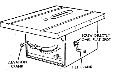
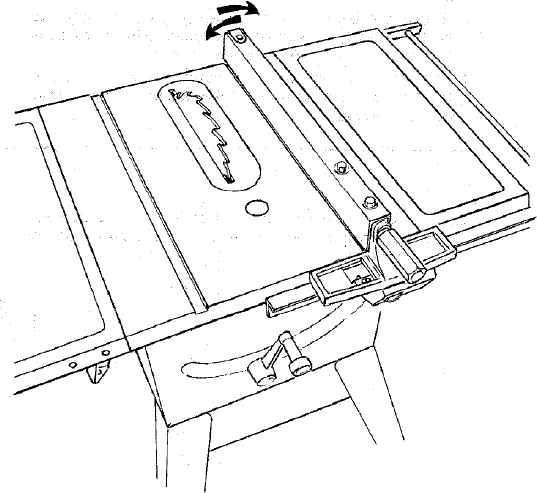
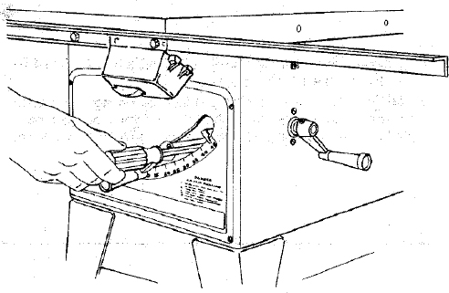
INSTALLING TILT CRANK
- Line up set screw in crank with FLAT SPOTS on shaft … tighten screws using 1/8 in. set screw wrench furnished with saw.
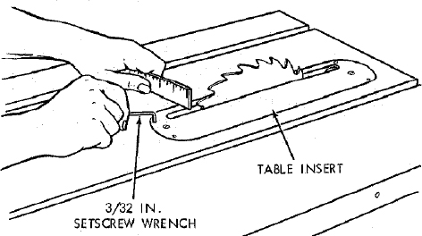
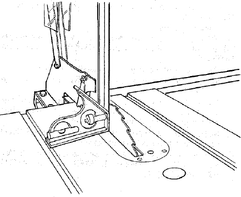
CHECKING TABLE INSERT
- Insert should be flush with table top. Check as shown – and adjust the four setscrews as necessary.
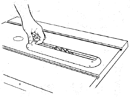
Insert forefinger into table-insert slot and pull upward to remove insert.
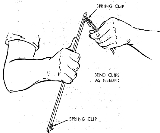
Replace insert. If clips do not hold insert securely, remove insert and bend clips.
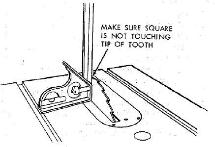
CHECKING BLADE SQUARENESS TO TABLE
IMPORTANT: BLADE must be SQUARE (90°) to TABLE, in order to proceed with assembly.
Turn ELEVATION crank clockwise until blade is up as high as it will go.
Check for BLADE SQUARENESS … if blade is not square to table, adjust it at this time.
NOTE: The combination square must be “true” – see start of “Unpacking and Checking Contents” section on page 6 for checking method.
Refer to “BLADE TILT, OR SQUARENESS OF BLADE TO TABLE” adjustments on page 30.
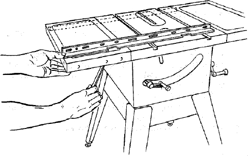
ASSEMBLING STEEL LEGS
NOT SUPPLIED IN CANADA
NOTE: Steel Legs are furnished with Model 113.299040 and 113.298470. From among the loose parts, find the following Hardware:
24 Truss Head Screws, 1/4 in. - 20 × 5/8 in. long (top of screw is rounded)
24 Lockwashers, 1/4 in. External Type (approx. dia. of hole 1/4 in.)
24 Hex Nuts, 1/4 in. - 20 (approx. dia. of hole 1/4 in.)
8 Hex Nuts, 1/2 in. - 13 (approx. dia. of hole 1/2 in.)
4 Leveling feet.
Assemble the legs as shown …
- Insert the Truss Head Screws through the holes in the legs, then through the holes in the stiffeners. MAKE SURE THE SCREWS GO THROUGH THE HOLES IN THE SIDE STIFFENERS MARKED “X”.
- Install the lockwashers … screw on the nuts but do not tighten until completely assembled.
- Install leveling feet.
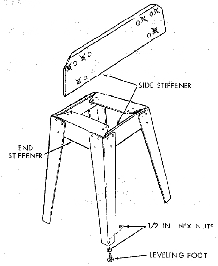
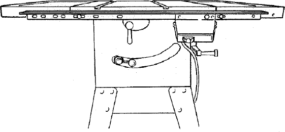
MOUNTING SAW
From among the loose parts, find the following hardware:
4 Hex Head Screws, 5/16 in. - 18 × 1-1/4 in. long.
4 Hex Nuts, 5/16 in. - 18 (approx. dia. of hole 5/16 in.)
4 Lockwashers, 5/16 in. External Type (approx. dia. of hole, 5/16 in.)
8 Flat Washers, (dia. of hole 11/32 in.)
Place saw on legs so that holes in bottom of saw line up with holes in top of legs.
Install screws, washers and nuts as shown.
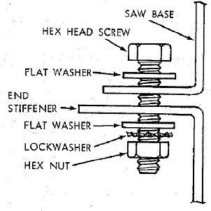
If you mount the saw on any other bench, make sure that there is an opening in the top of the bench the same size as the opening in the bottom of the saw so that the sawdust can drop through. Recommended working height is 33 to 37 inches from the top of the saw table to the floor.
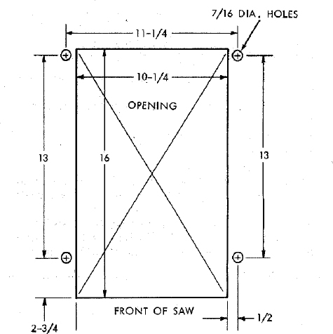
NOTE: All dimensions in inches
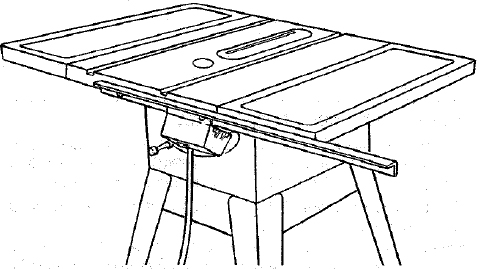
ATTACHING TABLE EXTENSIONS
If you received Table Extensions with your saw (two furnished with Model No. 113.299040 or one furnished with Model No. 113.298470) attach them at this time.
If you have only one Table Extension, it may be attached to either side.
NOTE: When the Table Extension is attached to the left side, it offers more support to the workpiece, especially when crosscutting or mitering long boards. When attached to the right side, it offers more support when cutting wide panels.
If you attach the Extension to the left side, be sure to construct the Auxiliary Fence/Work Support and Push Block shown on page.
From among the loose parts find the following hardware:
8 Hex Head Screws 5/16 in. - 18 × 1-1/4 in. long
8 Lockwashers, 5/16 in. External Type (approx. dia. of hole 5/16 in.)
8 Hex Nuts, 5/16 in. - 18 (approx. dia. of hole 5/16 in.)
Insert screws through holes in EXTENSION then through table. Install lockwashers and screw on the nuts … DO NOT TIGHTEN.
Align front edge of extension with front edge of saw table. Pull Extension UPWARDS above table surface … SLIGHTLY TIGHTEN SCREWS using 1/2 in. wrench.
Using small block of hardwood and hammer, tap extension DOWNWARDS at front, center & rear, until it is EVEN with table surface … TIGHTEN SCREWS.
Lay REAR FENCE GUIDE BAR on table to act as a straightedge. If outer edge of extension is higher or lower than table surface;
- Slightly loosen nuts holding bracket to extension using 7/16 in. wrench.
- Move end of extension up or down until outer edge is even with table surface … check with GUIDE BAR … tighten nuts.
- Recheck INNER edge of extension to make sure it has not moved … readjust, if necessary.
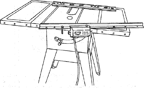
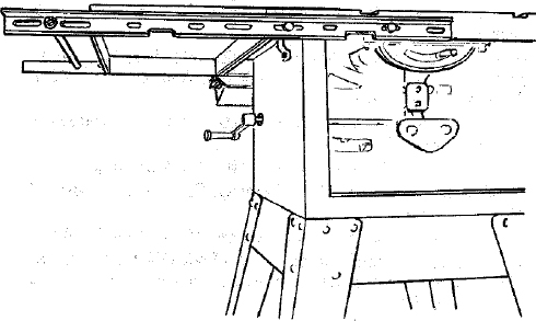
INSTALLING RIP FENCE GUIDE BARS
From among the loose parts find the following hardware:
2 Hex. Head Screws, 5/16 in. - 18 × 1-1/2 in. long
2 Hex. Head Screws, 5/16 in. -18 × 1 in. long
4 Hex. Nuts, 5/16 in. - 18 (approx. dia. of hole 5/16 in.)
4 External Lockwashers, 5/16 in. (approx. dia. of hole 5/16 in.)
2 Spacers, 3/4 in. dia. × 1/2 in. long
2 Self-threading nuts
Lay guide bars on table.
NOTE: The various holes in the bars allow them to be repositioned on the saw and also makes them adaptable to other models.
Insert 1-1/2 in. long screw through the THIRD hole from the LEFT IN THE FRONT BAR … insert another 1-1/2 in. long screw through LARGE hole in SWITCH BRACKET then through SEVENTH hole in bar. Hold them in place with a piece of masking tape from the underside.
Place spacers on screws.
- Insert bolts through holes in middle and on right side of front of saw table … install lockwashers and nuts. DONT SCREW NUTS ON ALL THE WAY, just get them started on the screws.
Remove the 3 screws from rear of table extension.
Insert 1 in. long screws in SECOND and FOURTH holes of rear bar and attach to table the same way.
Insert ends of FENCE GUIDE BAR ROD through round holes at outer end of bars.
NOTE: The ends of the ROD are not threaded … . the SELF THREADING NUTS will cut threads on the rod as they are screwed on.
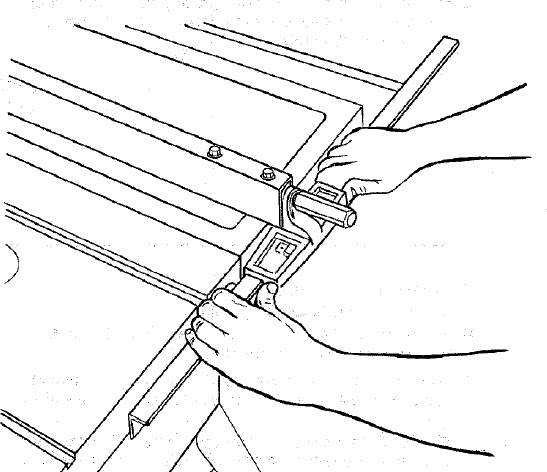
- Hold rod with one hand and with a 7/16 in. wrench or pliers start screwing on ONE of the nuts only A TURN OR TWO … screw on other nut the same way.
- Using TWO 7/16 in. wrenches or pliers tighten both of the nuts.
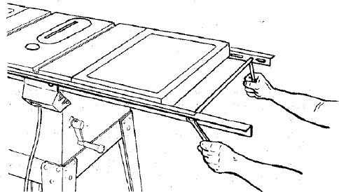
- Slide the bars so that screws are in the MIDDLE of the slotted holes.
- Position rip fence over miter gauge groove, holding up the rear end while engaging front end with bar … lower fence onto table.
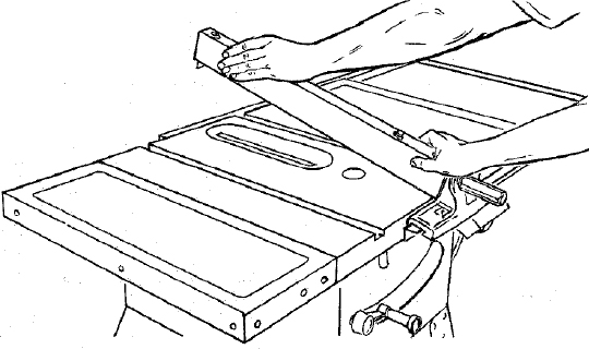
Raise blade all the way up.
Carefully move fence against blade.
Move front bar until “0” mark on rip scale is approximately at tip of pointer.
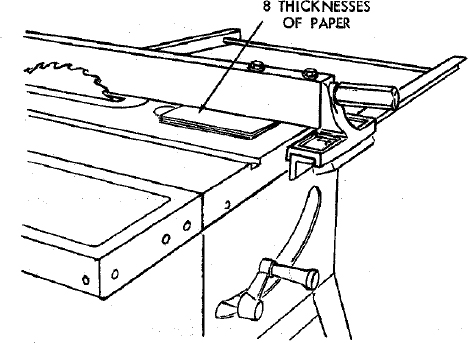
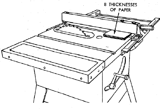
Move FRONT bar upwards until fence is approximately 1/32 in. above table … tighten screw at left end of bar.
NOTE: Fold a piece of newspaper making 8 thicknesses and place between rip fence and table to act as a spacer. This will hold the fence off of the table approx. 1/32 in.
Adjust rear bar so that the fence is approximately 1/32 in. above table make sure it is square with fence guide bar rod … tighten screw at end of bar.
Replace screws in rear of table extension … be sure top surface of extension is PARALLEL to top surface of rear guide bar.
- Move fence to RIGHT edge of table … make sure it is approx. 1/32 in. above table at front and rear and tighten screws.
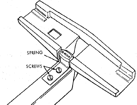
ALIGNING RIP FENCE
The fence should slide easily along the bars and always remain in alignment (parallel to sawblade and miter gauge grooves).
The alignment is maintained by a spring underneath the fence which bears against the front guide bar.
To move the fence, loosen the lock handle and grasp the fence with one hand at the front.
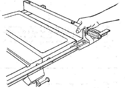
For very close adjustments, grasp the guide bar with both hands and move the fence with your thumbs.
Place fence on saw but DO NOT LOCK IT.
Move the REAR END of the fence slightly to the right or left … when you release it, the fence should “spring” back to its original position.
If it does not, the spring pressure must be INCREASED.
- Loosen the screws.
- Move Spring slightly toward front of fence.
If the fence does not slide easily along the bars, the pressure of the spring can be REDUCED.
- Loosen the screws.
- Move spring slightly toward rear of fence … tighten screws.
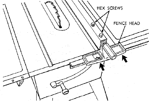
- The rip fence must be PARALLEL with the sawblade and Miter Gauge grooves … Move fence until it is along side of groove. Do NOT LOCK IT. It should be parallel to groove. If it is not;
- Loosen the two “Hex. Head Screws.”
- Hold fence head tightly against bar … move end of fence so that it is parallel with groove.
- Alternately tighten the screws.
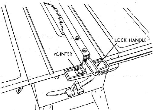
ADJUSTING RIP SCALE POINTER
Turn ELEVATION crank counterclockwise until blade is up as high as it will go.
IMPORTANT: BLADE must be SQUARE (90°) to TABLE, in order to ALIGN rip fence.
Position fence on right side of sawblade so that it touches the sides of the teeth … tighten lock handle.
Loosen screw holding the pointer … adjust pointer so that it points to “0” … tighten screw.
NOTE: If you cannot adjust pointer so that it points to “0”, loosen the screws holding the front guide bar and move the guide bar.
REPOSITIONING RIP FENCE GUIDE BARS
NOTE: If most of your work does not require 24 in. of rip capacity, the bars may be reposi tioned to allow 12 in. of rip capacity to the right, or 10-1/2 n. to the left. The rip scale, however, only reads to the right.
There is a second set of numerals reading from 0 to 12 in. to the right which can be used when the rails are repositioned.
- Attach FRONT bar by inserting bolts through FIFTH and NINTH holes in bar and through RIGHT and LEFT holes in table.
- Attach REAR bar using SIXTH and EIGHTH holes in bar.
NOTE: Remove screws from Table Extensions … the ones closest to the table. Reinstall them after attaching guide bar. If extension is used on right side of saw, remove the Guide Bar Rod.
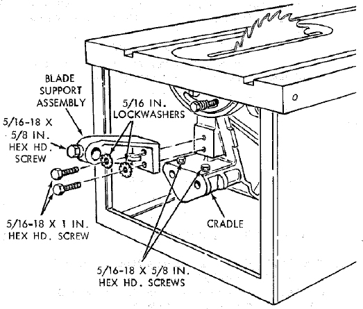
INSTALLING BLADE GUARD
From among the loose parts, find
2 Hex Head Screws, 1/4 in. - 20 × 5/8 in. long
2 Hex Head Screws, 5/16 in. - 18 × 5/8 in. long
2 Hex Head Screws, 5/16 in. - 18 × 1 in. long
2 Hex Nuts, 1/4 in. - 20 (approx. dia. of hole 1/4 in.)
2 Lockwashers, 1/4 in. External Type (approx. dia. of hole 1/4 in.)
2 Lockwashers, 5/16 in. External Type (approx. dia. of hole 5/16 in.)
1 Thumbscrew
Blade Guard Support
Spreader Support
Spreader Rod
Lower the blade.
Screw the two MOTOR MOUNT CLAMP SCREWS part way into cradle.
Attach BLADE GUARD SUPPORT … DO NOT TIGHTEN screws.
- Insert SPREADER ROD into SPREADER SUPPORT until pin fits into notch. Insert Thumbscrew and tighten it.
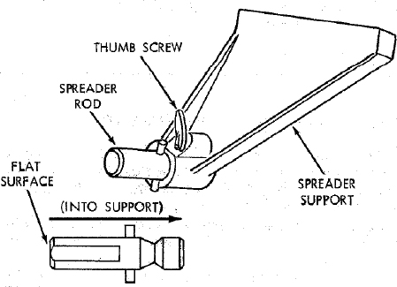
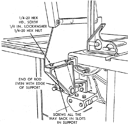
Slide SPREADER ROD into BLADE GUARD SUPPORT until end of ROD is even with edge of SUPPORT … Tighten Hex Head Screw in support.
Attach SPREADER to SPREADER SUPPORT so that screws are all the way back in the SLOTS of SUPPORT … tighten screws.
Raise ANTI-KICKBACK PAWL (hold it in place with a piece of masking tape)
… align spreader SQUARE to table
… Tighten both HEX HEAD SCREWS.
- Raise blade all the way up … make sure it is square with table.
- Raise Blade Guard … lift up both ANTI-KICKBACK PAWLS … insert one of the SETSCREW WRENCHES in the notches to hold the pawls out of the way.
- Lay blade of square or other straightedge alongside of blade.
- Loosen Hex Head Screw in BLADE GUARD SUPPORT and move spreader so that it touches blade of square … tighten screw.
- NOTE: The spreader is now square with the table and approximately in line with the sawblade. The spreader requires further adjustment to align it PARALLEL to the blade and in the MIDDLE of the cut (KERF) made by the sawblade.
IMPORTANT: The SPREADER must always be PARALLEL to the sawblade and in the MIDDLE of the cut (KERF) made by the sawblade.
NOTE: The spreader is thinner than the width of the KERF by approximately six thicknesses of paper.
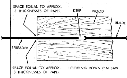
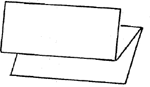
Make two folds in a small piece (6 × 6 in.) or ordinary NEWSPAPER making three thicknesses.
The folded paper will be used as a “spacing gauge”.
Place RIP FENCE on table …
CAREFULLY move it against blade so that it is parallel to the blade, and just TOUCHES tips of saw teeth … tighten RIP FENCE LOCK KNOB HANDLE.
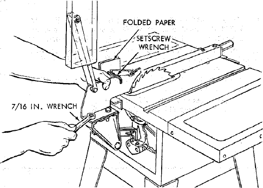
Insert folded paper between SPREADER and FENCE … hold spreader flat against fence … tighten screws using 7/16 in. wrench.
To remove BLADE GUARD AND SPREADER, loosen THUMBSCREW … DO NOT LOOSEN OTHER SCREWS.
MOUNTING THE MOTOR
NOTE: Motor is included with Model 113.299040 and 113.298470.
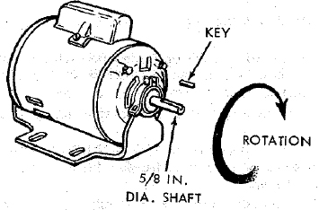
CHECK MOTOR ROTATION
- The motor must rotate CLOCKWISE when viewed from the 5/8 in. shaft.
- MAKE SURE “KEY” IS REMOVED FROM SHAFT.
- Place the motor on your workbench or on the floor.
- Stand clear of the motor and plug the cord into a properly grounded outlet (See “Motor Specifications and Electrical Requirements” Section) Notice the rotation of the pulley. If it is not turning CLOCKWISE, REMOVE the plug from the outlet, and change the rotation of the motor according to the instructions furnished with the motor.
WARNING: FOR YOUR OWN SAFETY, MAKE SURE PLUG IS NOT CONNECTED TO POWER SOURCE OUTLET WHEN CHANGING MOTOR ROTATION.
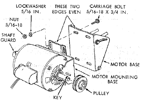
From among the loose parts, find the following hardware:
4 Carriage Bolts, 5/16 in. - 18 × 3/4 in. long
4 Hex. Nuts, 5/16 in. - 18 (approx. dia. of hole 5/16 in.)
4 Lockwashers, 5/16 in. External Type (approx. dia. of hole 5/16 in.)
Remove Blade Guard and Spreader.
Place motor on MOTOR BASE … insert bolts through holes in base … then through the motor. Install lockwashers, and nuts.
Position motor so that edge of MOTOR FOOT and MOTOR BASE are even … slide motor all the way to the RIGHT … tighten the four nuts.
Loosen set screw in motor pulley using 5/32 in. setscrew wrench. Slide pulley on shaft with HUB away from motor. DO NOT TIGHTEN SETSCREW.
Install 3/16 in. square key (furnished with motor) in grooves in pulley and motor shaft. DO NOT TIGHTEN SETSCREW.
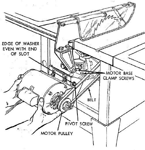
- Lift motor and insert the TWO PINS on motor base into HOLES in cradle … push motor in as far as it will go.
- Lower the blade … install belt on saw pulley and motor pulley.
- Sight along edges of both pulleys and move motor pulley so that belt is parallel to the edges of both pulleys … tighten the setscrew in the motor pulley.
- IMPORTANT: Measure the distance from end of motor shaft to pulley …mark this dimension down; you will need it later when reinstalling the pulley.
- Make sure blade is 90° to table …raise it all the way up.
- Lift motor until edge of washer is even with end of slot … tighten pivot screw. In this position, pull motor toward you (pins will slide out of cradle) until belt is TIGHT … tighten the two MOTOR BASE CLAMP SCREWS.
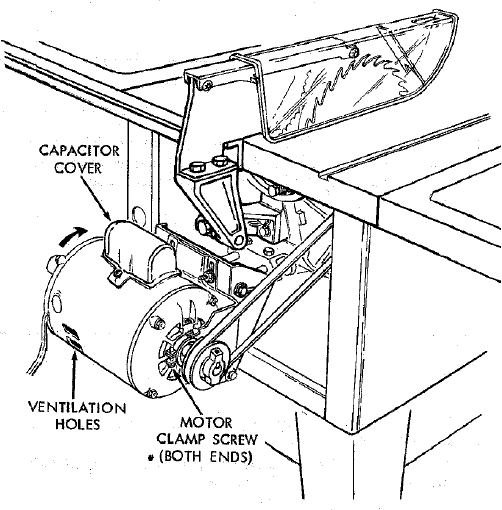
- Loosen Pivot Screw slightly.
- Lower the saw blade all the way down.
- IMPORTANT: Motor should pivot freely downward as blade is lowered. If it does not, LOOSEN the PIVOT SCREW some more.
- Pivot screw must be adjusted only tight enough to allow motor to pivot FREELY as blade is raised or lowered. This will maintain constant tension on belt.
- Loosen the two MOTOR CLAMP SCREWS on each end of motor. Rotate the motor so that the CAPACITOR COVER is on top … tighten the screws. The ventilation holes are now facing downward which will help prevent sawdust from entering motor.
INSTALLING BELT GUARD
- Remove the belt and motor pulley.
- Screws furnished with guard are “self threading” … screw them into holes in BELT GUARD SUPPORT BRACKET, then remove them.
- Position BELT GUARD SUPPORT BRACKET and BELT GUARD SUPPORT as shown and install the screws … make sure motor shaft is in CENTER of hole in SUPPORT.
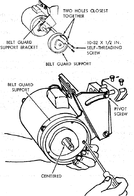
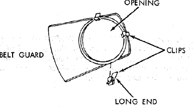
- Install three CLIPS (furnished with guard) 90° apart starting with one clip at the end of the guard as shown … LONG END of clip facing AWAY from you.
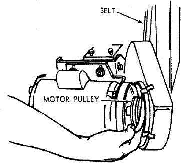
- Reinstall motor pulley the same way it was when you aligned the belt.
- Place belt on SAW’ PULLEY … insert end of belt through opening in END of guard.
- Slip belt over motor pulley.
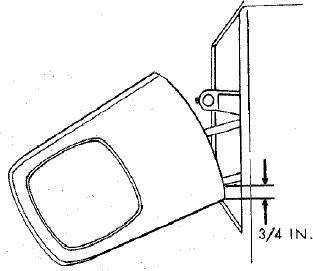
Press guard onto support so that bottom of guard is approximately 3/4 in. away from belt.
NOTE: To remove guard, lift up on LONG TABS of clips … pull guard outward. The clips should remain on the BELT GUARD SUPPORT.
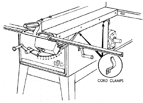
PLUGGING IN MOTOR
- From among the loose parts, find two Pan Head Sheet Metal Screws, 3/8 in. long, and two cord clamps.
- Attach clamps to right side of saw cabinet.
- Route motor cord and power cord inside of clamps.
- Plug motor cord into outlet on back of switch box.
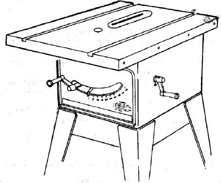
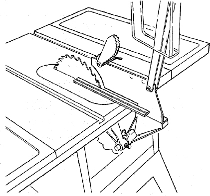
GETTING TO KNOW YOUR SAW
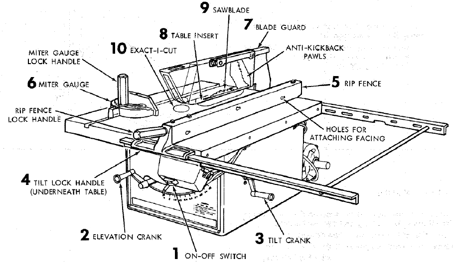
1 ON-OFF SWITCH
CAUTION: Before turning switch on, make sure the blade guard is correctly installed and operating properly.
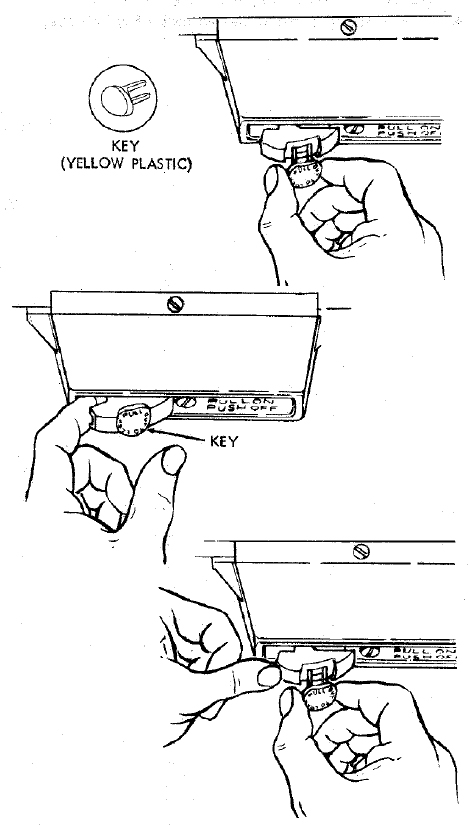
The On-Off Switch has a locking feature. THIS FEATURE IS INTENDED TO PREVENT UNAUTHORIZED AND POSSIBLE HAZARDOUS USE BY CHILDREN AND OTHERS.
TO turn saw ON … stand to either side of the blade never in line with it … insert finger under switch lever and pull END of lever out.
After turning switch ON, always allow the blade to come up to full speed before cutting.
Do not cycle the motor switch on and off rapidly, as this may cause the sawblade to loosen. In the event this should ever occur, allow the sawblade to come to a complete stop and retighten the arbor nut normally, not excessively. Never leave the saw while the power is “ON”.
TO turn saw OFF … PUSH lever in. Never leave the saw until the cutting tool has come to a complete stop.
TO lock switch in OFF position … hold switch IN with one hand … REMOVE key with other hand.
WARNING: FOR YOUR OWN SAFETY, LOWER BLADE OR OTHER CUTTING TOOL BELOW TABLE SURFACE. (IF BLADE IS TILTED, RETURN IT TO VERTICAL (90°) POSITION). ALWAYS LOCK THE SWITCH “OFF”. WHEN SAW IS NOT IN USE … REMOVE KEY AND KEEP IT IN A SAFE PLACE … ALSO … IN THE EVENT OF A POWER FAILURE (ALL OF YOUR LIGHTS GO OUT) TURN SWITCH OFF … LOCK IT AND REMOVE THE KEY. THIS WILL PREVENT THE SAW FROM STARTING UP AGAIN WHEN THE POWER COMES BACK ON.
ELEVATION CRANK … elevates or lowers the blade. Turn clockwise to elevate … counterclockwise to lower.
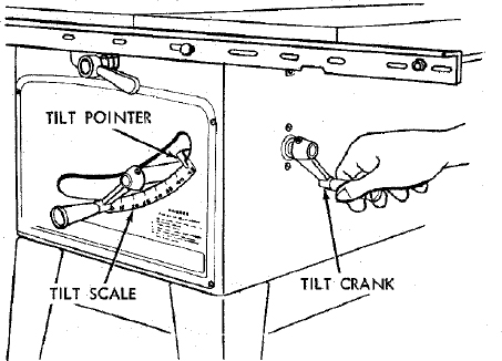
TILT CRANK … tilts the blade for bevel cutting. Turn clockwise to tilt toward left … counterclockwise to tilt toward right.
When the blade is tilted to the LEFT as far as it will go, it should be at 45° to the table and the bevel pointer should point 45°.
NOTE: There are LIMIT STOPS inside the saw which prevent the blade from tilting beyond 45° to the LEFT and 90° to the RIGHT. (See “Adjustments” section “Blade Tilt, or Squareness of Blade to Table”).
TILT LOCK HANDLE … locks the blade in the desired tilt position. To loosen, turn counterclockwise. Push handle in and turn it to another position if necessary in order to tighten or loosen.
RIP FENCE … is locked in place by tightening the lock handle. To move the fence, loosen the handle and grasp the fence with one hand at the front.
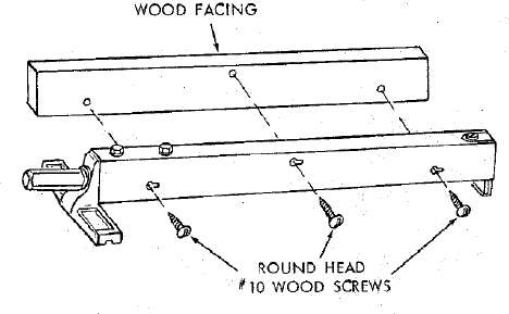
Holes are provided in the rip fence for attaching a wood facing when using the dado head, or molding head.
Select a piece of smooth straight wood approx. 3/4 in. thick and the same size as the rip fence.
Attach it to the fence with three Round Head #10 Wood Screws 2 in. long. To remove the facing, loosen the screws, slide the facing forward and pull the screws through the round holes.
MITER GAUGE … head is locked in position for crosscutting or mitering by tightening the lock handle. ALWAYS LOCK IT SECURELY WHEN IN USE.
There are two holes for the stop pin at the 45 degree right and left positions for conveniently setting the Miter Gauge to cut miters.
NOTE: The holes for the stop pin and the graduations are manufactured to very close tolerances which provide accuracy for average woodworking. In some cases where extreme accuracy is required, when making angle cuts, for example, make a trial cut and then recheck it.
If necessary, the miter gauge head can then be swiveled slightly to compensate and then locked.
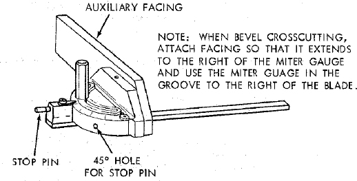
Holes are provided in the miter gauge for attaching an AUXILIARY FACING to make it easier to cut long pieces.
Select a suitable piece of smooth straight wood … drill two holes through it and attach it with small screws and nuts. The nuts go inside of the miter gauge. Or drill 1/4 in. holes all the way through the head. Then you can attach the facing with wood screws.
NOTE: When bevel crosscutting, attach facing so that it extends to the right of the miter gauge and use the miter gauge in the groove to the right of the blade.
BLADEGUARD must always be in place and working properly for all thru-sawing cuts. That is, all cuts whereby the blade cuts completely through the workpiece.
To remove the guard for special operations, loosen the thumbscrew and slide the guard off of the rod. DO NOT DISTURB THE SETTING OF THE ROD.
When replacing the guard, make sure the PIN in the rod engages with the NOTCH in the spreader support. Make sure thumbscrew is tightened securely.
TABLE INSERT is removable for removing or installing blades or other cutting tools.
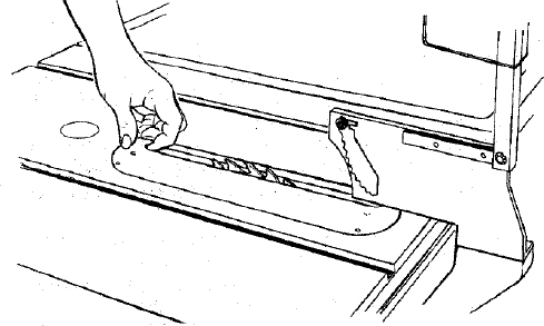
WARNING: FOR YOUR OWN SAFETY, TURN SWITCH “OFF” AND REMOVE PLUG FROM POWER SOURCE OUTLET BEFORE REMOVING INSERT.
- Lower the blade below the table surface.
- Raise blade guard.
- Lift insert from front end, and pull toward front of saw.
NEVER OPERATE THE SAW WITHOUT THE PROPER INSERT IN PLACE. USE THE SAW BLADE INSERT WHEN SAWING … USE THE COMBINATION DADO MOLDING INSERT WHEN DADOING OR MOLDING.
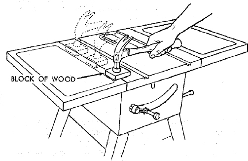
REMOVING AND INSTALLING SAWBLADE.
WARNING: FOR YOUR OWN SAFETY, TURN SWITCH “OFF” AND REMOVE PLUG FROM POWER SOURCE OUTLET BEFORE REMOVING OR INSTALLING SAWBLADE.
- Raise Blade Guard … remove insert.
- To REMOVE blade, place a block of wood against front of blade … PULL arbor wrench toward you to LOOSEN arbor nut.
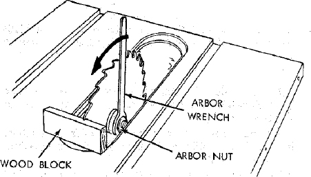
BLADE GUARD NOT SHOWN FOR PICTURE CLARITY
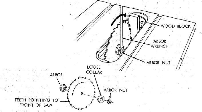
- To TIGHTEN arbor nut, place a block of wood against rear of blade … PUSH wrench away from you.
When installing the blade … make sure the teeth are pointing toward the front of the saw … and that the blade and collars are clean, and free from any burrs.
The HOLLOW side of the collar must be against the blade.
Always tighten the arbor nut securely.
NOTE: When using the Dado or Molding Head, it is not necessary to install the loose collar.
BLADE GUARD NOT SHOWN FOR PICTURE CLARITY
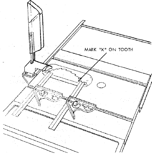
- EXACT-I-CUT
The “yellow” plastic disc imbedded in the table in front of the sawblade, is provided for marking the location of the “sawcut” on the workpiece.
- Check disc … if it is above table surface, place a piece of hardwood on top of it and tap it down.
- With blade 90° (square to table) cut off a piece of wood.
- Pull miter gauge back until wood is over disc. Using very sharp pencil, mark a line on disc.
- With miter gauge in right hand groove, follow same procedure and mark another line on disc.
- These lines indicate the “path” of the cut (kerf) made by the sawblade.
- When cutting the workpiece, line up mark on workpiece with line on disc.
BLADE GUARD NOT SHOWN FOR PICTURE CLARITY
BASIC SAW OPERATION
USING THE MITER GAUGE
CROSSCUTTING, MITER CUTTING, BEVEL CUTTING, COMPOUND MITER CUTTING and when RABBETING across the end of a narrow workpiece, THE MITER GAUGE IS USED.
WARNING: FOR YOUR OWN SAFETY, ALWAYS OBSERVE THE FOLLOWING SAFETY PRECAUTIONS IN ADDITION TO THE SAFETY INSTRUCTIONS ON PAGES 2, 3, and 4.
Never make these cuts freehand (without using the miter gauge or other auxiliary devices) because the blade could bind in the cut and cause a KICKBACK or cause your fingers or hand to slip into the blade.
Always lock the miter gauge securely when in use.
Remove rip fence from table.
Make sure blade guard is installed for all “thru-sawing” operations (when sawblade cuts entirely thru the thickness of the workpiece.) Replace guard IMMEDIATELY after completion of dadoing, molding or rabbeting cuts.
Have blade extend approximately 1/8 in. above top of workpiece. Additional blade exposure would increase the hazard potential.
Do not stand directly in front of the blade in case of a THROWBACK (Small cut-off piece caught by the back of the blade and thrown toward the operator). Stand to either side of the blade.
Keep your hands clear of the blade and out of the path of the blade.
If blade stalls or stops while cutting, TURN SWITCH OFF before attempting to free the blade.
Do not reach over or behind the blade to pull the workpiece through the cut … to support long or heavy workpieces … to remove cut-off pieces of material or FOR ANY OTHER REASON.
Do not pick up small pieces of cut-off material from the table. REMOVE them by pushing them OFF the table with along stick. Otherwise they could be thrown back at you by the rear of the blade.
Do not remove small pieces of cut-off material that may become TRAPPED inside the blade guard while the saw is RUNNING. THIS COULD ENDANGER YOUR HANDS or cause a KICKBACK.
Turn the saw OFF. After the blade has stopped turning, lift the guard and remove the piece.
WORK HELPERS
Before cutting any wood on your saw, study all of the “Basic Saw Operations”.
Notice that in order to make some of the cuts, it is necessary to use certain devices “Work Helpers” like the Push Stick, the Push Block and the Auxiliary Fence/Work Support, which you can make yourself.
After you have made a few practice cuts, make up these “helpers” before starting any projects. Make the “Push Stick” first. To rip the piece for the push stick, start out with a wide board, say 11-1/2 in. wide and set the rip fence 9-3/4 in. from the blade.
NOTE: All dimensions in inches
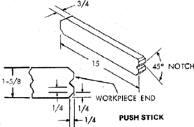
PUSH STICK AND PUSH BLOCK
Make the Push Stick using a piece of 1 × 2.
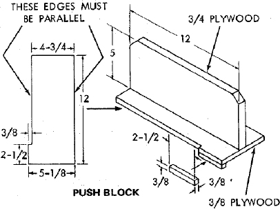
Make the Push Block using a piece of 3/8 in. and 3/4 in. plywood.
The small piece of wood 3/8 in. × 3/8 in. × 2-1/2 in. should be GLUED to the plywood … DO NOT USE NAILS. This is to prevent dulling the sawblade in the event you mistakingly cut into the push block.
Position the handle in the center of the plywood and fasten together with glue and woodscrews.
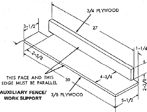
AUXILIARY FENCE/WORK SUPPORT
Make one using a piece of 3/8 in. and 3/4 in. plywood. Fasten together with glue and woodscrews.
NOTE: Since the Push Block is used with the Auxiliary Fence, the 4-3/4 in. dimensions must be held identical on both the pieces.
NOTE: All dimensions in inches
NOTE: All dimensions in inches
CROSSCUTTING
CROSSCUTTING is known as cutting wood across the grain, at 90°, or square with both the edge and the flat side of the wood. This is done with miter gauge set at “0”.
The graduations on the miter gauge provide accuracy for average woodworking. In some cases where extreme accuracy is required, when making angle cuts, for example, make a trial cut and then recheck it with an accurate square, or protractor.
If necessary, the miter gauge head can be swiveled slightly to compensate for any inacurracy.
NOTE: The space between the miter gauge bar and the groove in the table is held to a minimum during manufacturing.
For maximum accuracy when using the miter gauge, always “favor” one side of the groove in the table. In other words, don’t move the miter gauge from side to side while cutting, but keep one side of the bar riding against one side of the groove.
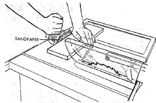
NOTE: Glue a piece of sandpaper to the face of the miter gauge head. This will help prevent the workpiece from “creeping” while it is being cut.
The Hold-Down Clamp (Optional Accessory) should be used on the miter gauge for greater accuracy.
The miter gauge may be used in either of the grooves in the table. Make sure it is locked.
When using the miter gauge in the LEFT hand groove, hold the workpiece firmly against the miter gauge head with your left hand, and grip the lock handle with your right.
When using the RIGHT Hand groove, hold the workpiece with your right hand and the lockhandle with your left hand.
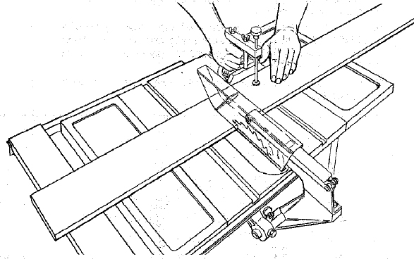
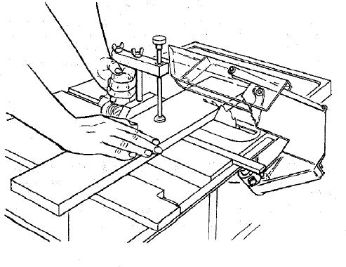
When cutting long workpieces, invert AUXILIARY FENCE/WORK SUPPORT and position it on top of the guide bars to support the workpiece as near to the end as possible.
Use the Hold-Down Clamp (Optional Accessory) on the miter gauge for greater accuracy.
REPETITIVE CUTTING
REPETITIVE CUTTING is known as cutting a quantity of pieces the same length without having to mark each piece.
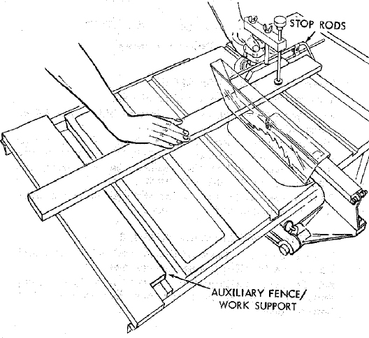
- Use the Stop Rods (optional accessory) only for cutting duplicate pieces 6 in. long and longer.
- DO NOT FEED workpiece with RIGHT Hand, merely guide it, making sure that it does not bind or pinch the sawblade.
When making repetitive cuts from a long workpiece, make sure it is supported.
Use the AUXILIARY FENCE / WORK SUPPORT for additional support of the workpiece.
Lay it across the guide bars to support the workpiece as near to the end as possible.
Use the Hold-Down Clamp (Optional Accessory) on the miter gauge for greater accuracy.
NEVER USE THE RIP FENCE AS A LENGTH STOP BECAUSE THE CUTOFF PIECE COULD BIND BETWEEN THE FENCE AND THE BLADE CAUSING A KICKBACK.
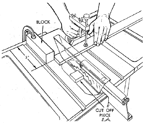
When making repetitive cuts shorter than 6 in., clamp a block of wood 3 in. long to the table to act as a length stop.
CAUTION: When clamping the block, make sure that the end of the block is well in front of the sawblade. Be sure it is clamped securely.
Slide the workpiece along the miter gauge until it touches the block … hold it securely or clamp it with the Hold-Down Clamp (Optional Accessory).
Make the cut … pull the workpiece back … push the cut off piece off the table with a long push stick … DO NOT ATTEMPT TO PICK IT UP AS THIS COULD ENDANGER YOUR HANDS.
MITER CUTTING
MITER CUTTING is known as cutting wood at an angle other than 90° with the edge of the wood. Follow the same procedure as you would for crosscutting.
Adjust the miter gauge to the desired angle, and lock it.
The miter gauge may be used in either of the grooves in the table.
When using the miter gauge in the LEFT Hand groove, hold the workpiece firmly against the miter gauge head with your left hand, and grip the lock handle with your right.
When using the RIGHT hand groove, hold the workpiece with your right hand and the lockhandle with your left hand.
Use the Hold-Down Clamp (Optional Accessory) on the miter gauge for greater accuracy.
BEVEL CROSSCUTTING
BEVEL CROSSCUTTING is the same as crosscutting except that the wood is also cut at an angle … other than 90° with the flat side of the wood.
Adjust the blade to the desired angle.
Use the Miter Gauge in the groove to the RIGHT of the blade. It cannot be used in the groove to the LEFT because the blade guard will interfere. Hold the workpiece with your right hand and the lockhandle with your left hand.
Use the AUXILIARY FENCE/WORK SUPPORT for additional support of the workpiece.
Lay it across the guide bars to support the workpiece as near to the end as possible.
Use the Hold-Down Clamp (Optional Accessory) on the miter gauge for greater accuracy.
COMPOUND MITER CUTTING
COMPOUND MITER CUTTING is a combination of miter cutting and bevel crosscutting. The cut is made at an angle other than 90° to both the edge and the flat side of the wood.
Adjust the miter gauge and the blade to the desired angle … Make sure miter gauge is locked.
USING THE RIP FENCE
RIPPING, BEVEL RIPPING, RESAWING AND RABBETING are performed using the RIP FENCE together with the AUXILIARY FENCE/WORK SUPPORT, PUSH STICK OR PUSH BLOCK.
WARNING: FOR YOUR OWN SAFETY, ALWAYS OBSERVE THE FOLLOWING SAFETY PRECAUTIONS IN ADDITION TO THE SAFETY INSTRUCTIONS ON PAGES 2, 3, and 4.
Never make these cuts FREEHAND (without using the rip fence or auxiliary devices when required) because the blade could bind in the cut and cause a KICKBACK.
Always lock the rip fence securely when in use.
Remove miter gauge from table.
Make sure blade guard is installed for all thru-sawing type cuts. Replace the guard IMMEDIATELY following completion of resawing, rabbeting, dadoing, or molding operations.
Frequently check the action of the ANTI-KICKBACK PAWLS by passing the workpiece alongside of the spreader while saw is OFF.
Pull the workpiece TOWARD you. If the PAWLS do not DIG into the workpiece and HOLD it …the pawls must be REPLACED. See “Maintenance” section.
Have blade extend approximately 1/8 in. above top of workpiece. Additional blade exposure would increase the hazard potential.
Do not stand directly in front of the blade in case of a KICKBACK. Stand to either side of the blade.
Keep your hands clear of the blade and out of the path of the blade.
If the blade stalls or stops while cutting. TURN SWITCH OFF before attempting to free the blade.
Do not reach over or behind the blade to pull the workpiece through the cut … to support long or heavy workpieces to remove small cut-off pieces of material or FOR ANY OTHER REASON.
Do not pick up small pieces of cut-off material from the table. REMOVE them by pushing them OFF the table with a long stick. Otherwise they could be thrown back at you by the rear of the blade.
Do not remove small pieces of cut-off material that may become TRAPPED inside the blade guard while the saw is RUNNING. THIS COULD ENDANGER YOUR HANDS or cause a KICKBACK.
Turn the saw OFF. After the blade has stopped turning, lift the guard and remove the piece.
RIPPING
RIPPING is known as cutting a piece of wood with the grain, or lengthwise. This is done using the rip fence.
Position the fence to the desired WIDTH OF RIP and lock in place.
Before starting to rip, be sure
- Rip Fence is parallel to sawblade.
- Spreader is properly aligned with sawblade.
- Anti-Kickback pawls are functioning properly.
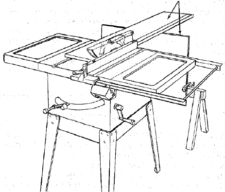
When ripping LONG BOARDS or LARGE PANELS, always use a work support.
A simple one can be made by clamping a piece of plywood to a sawhorse.
BEVEL RIPPING
When bevel ripping material 6 in. or narrower, use fence on the right side of the blade ONLY. This will provide more space between the fence and the sawblade for use of a push stick. If the fence is mounted to the left, the sawblade guard may interfere with proper use of a push stick.
ALWAYS SUPPORTLONG WORKPIECES
When “WIDTH OF RIP” is 6 in. and WIDER use your RIGHT Hand to feed the workpiece until it is clear of the table.
Use LEFT hand ONLY to guide the workpiece … do not FEED the workpiece with the left hand.
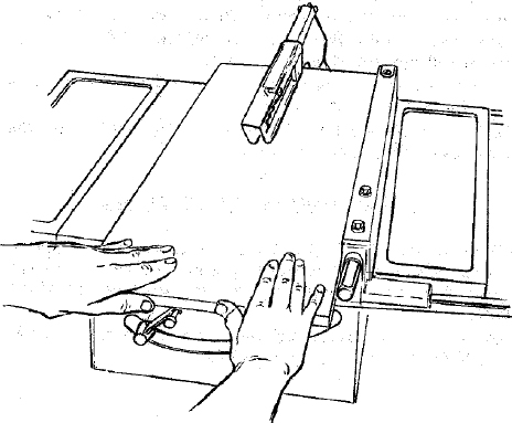
When “WIDTH OF RIP” is 2 in. to 6 in. wide USE THE PUSH STICK to feed the work.
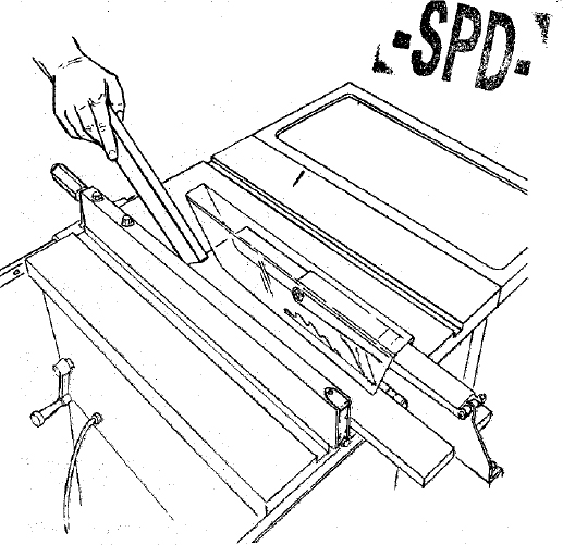
When WIDTH OF RIP is NARROWER than 2 in., the push stick CANNOT be used because the guard will interfere … USE the AUXILIARY FENCE/WORK SUPPORT and PUSH BLOCK.
Attach auxiliary fence to rip fence with two “C” clamps. Feed the workpiece by hand until the end is approx. 1 in. from the front edge of the table. Continue to feed using the PUSH BLOCK.
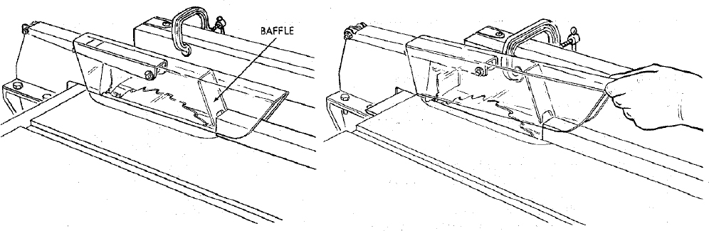
When ripping narrow strips that may enter the guard and strike the baffle, CAREFULLY raise guard only enough to clear the workpiece. Use Push Block to complete cut.
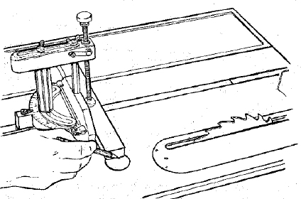
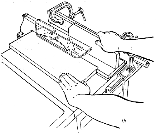
RESAWING
RESAWING is known as ripping a piece of wood through its thickness. NOTE: To RESAW a piece of wood wider than 3-3/8 in. … it will be necessary to remove the blade guard … and use the AUXILIARY FENCE/WORK SUPPORT. (See “Work Helpers”).
Do not attempt to resaw BOWED or WARPED material.
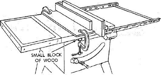
Clamp it to the table so that the workpiece will SLIDE EASILY but not TILT or MOVE SIDEWAYS without BINDING between the two fences.
Do not clamp directly to the bottom edge of the table because the “swivel” of the clamp will not grip properly. Place a small block or wood between the bottom edge of the table and the “C” clamp.
WARNING: FOR YOUR OWN SAFETY …
- DO NOT “BACK UP” (REVERSE FEEDING) WHILE RESAWING BECAUSE THIS COULD CAUSE A KICKBACK.
- INSTALL BLADE GUARD IMMEDIATELY UPON COMPLETION OF THE RESAWING OPERATION.
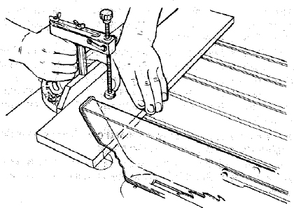
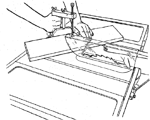
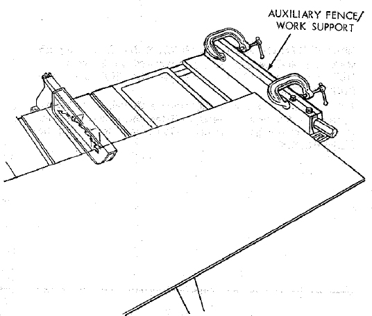
CUTTING PANELS
When cutting panels (whenever fence is positioned outside of table surface), ALWAYS use the AUXILIARY FENCE/WORK SUPPORT.
- Unlock fence and raise rear end.
- Position AUXILIARY FENCE as shown and attach it with two “C” clamps.
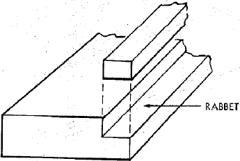
RABBETING
Rabbeting is known as cutting out a section of the corner of a piece of material.
To make a RABBET requires two cuts which do not go all the way through the material. Therefore the blade guard must be removed.
- Remove blade guard.
- Adjust rip fence and blade to required dimensions.
- Make first cut through edge. Follow resawing procedure.
- Remove auxiliary fence and make second cut.
- INSTALL BLADE GUARD IMMEDIATELY UPON COMPLETION OF RABBETING OPERATION.
Rabbet cuts can also be made using the dado head or molding head.
ADJUSTMENTS
WARNING: FOR YOUR OWN SAFETY, TURN SWITCH “OFF” AND REMOVE PLUG FROM POWER SOURCE OUTLET BEFORE MAKING ANY ADJUSTMENTS.
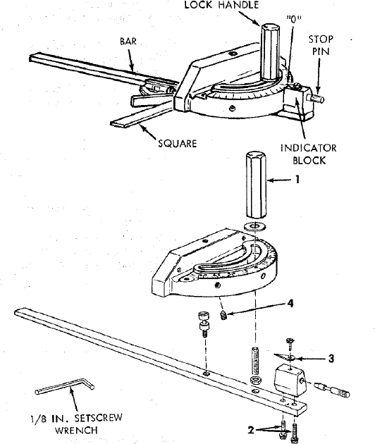
MITER GAUGE
NOTE: The holes for the stop pin and the graduations are manufactured to very close tolerances which provide accuracy for average woodworking. In some cases where extreme accuracy is required, when making angle cuts, for example, make a trial cut and then recheck it.
If necessary, the miter gauge head can be swiveled slightly to compensate for any inaccuracy.
Loosen the “handle” and pull “stop pin” OUT.
Swivel the head … position it at “0” … push the stop pin IN … lock the handle.
The HEAD should be square with the Bar and the pointer should point to “0”. Readjust the pointer if necessary.
If the head is not square with the bar, adjustments are required.
- Loosen the “handle” (1) and the “two screws” (2)
- Position the HEAD square with the BAR using a combination square.
- PUSH the STOP PIN into the hole in the head at “0” … push the pin into the hole and twist it. Lock the handle.
- Recheck with the square. If the head is still not square, loosen the screws (2) and readjust the INDICATOR BLOCK.
- With the head square with the bar and the pin pushed into the hole, adjust the pointer (3) to point to”0”.
- The miter gauge head must rest on top of the bar without being able to move up and down … yet it must swivel freely.
- The swiveling movement of the head can be adjusted by tightening or loosening the setscrew (4) … using the 1/8 in. setscrew wrench.
NOTE: The setscrew is located inside of the head. To reach it, swivel the head to 60 degrees and turn the miter gauge upside down.
HEELING ADJUSTMENT or PARALLELISM OF SAWBLADE TO MITER GAUGE GROOVE
While cutting, the material must move in a straight line PARALLEL to the SAWBLADE … therefore both the miter gauge GROOVE and the RIP FENCE must be PARALLEL to the SAWBLADE.
If the sawblade IS NOT parallel to the miter gauge groove, the blade will bind at one end of the cut. (This is known as “HEELING”).
To check for parallelism:
WARNING – FOR YOUR OWN SAFETY, TURN SWITCH “OFF” AND REMOVE PLUG FROM POWER SOURCE OUTLET.
- Raise blade all the way up … raise blade guard.
- Mark as “×” on one of the teeth which is SET (bent) to the LEFT.
- Place the head of a combination square in the GROOVE … adjust blade of square so that it just touches the tip of of the MARKED tooth.
- Move square to REAR, rotate blade to see if MARKED tooth again touches blade of square.
- If tooth touches square the same amount at FRONT and REAR … sawblade is PARALLEL to MITER GAUGE GROOVE.
- If tooth does not touch the same amount … the mechanism underneath must be adjusted to make the blade PARALLEL to GROOVE.
- Rear trunnion must be moved TOWARD the combination square if there is a space between marked tooth and end of square in step 4.
- Rear trunnion must be moved AWAY from the square if marked tooth pushes square out of position in the groove.
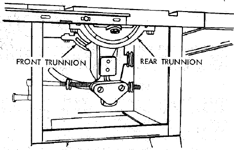
- Loosen all three screws that hold the rear trunnion and all three screws that hold the front trunnion.
NOTE: All six screws can be reached through back of saw. Use a 9/16-in. wrench. To reach left-hand front trunnion screw, tilt blade to 45°. After loosening screws reposition blade at 90°.
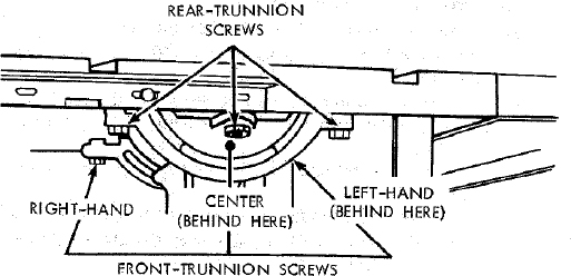
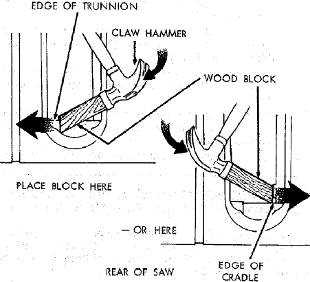
- Using a wood block and mallet as shown, move rear trunnion to right or left as required to realign the blade. If necessary, shift front trunnion in similar manner; but do NOT move front trunnion unless necessary. Recheck the alignment with the square, then securely retighten all six trunnion screws.
BLADE TILT, OR SQUARENESS OF BLADE TO TABLE
90° (SQUARE) and 45° (BEVEL) STOP COLLARS.
When the bevel pointer is pointing directly to the “O” mark on the bevel scale, the sawblade should make a SQUARE cut 90° to the table.
To check for SQUARENESS:
WARNING: FOR YOUR OWN SAFETY, TURN SWITCH “OFF” AND REMOVE PLUG FROM POWER SOURCE OUTLET.
- Raise blade all the way UP … raise blade guard.
- TILT blade a few degrees to the LEFT … now tilt blade back to the RIGHT as far as it will go.
- Place and ACCURATE square against blade. Make sure square is not touching the TIP of one of the saw TEETH.
- Operate the tilt-lock handle (COUNTERCLOCKWISE) to loosen the tilt clamp screw.
- NOTE: Handle is spring loaded for engagement with screw head ‒ must be pushed inward for disengagement whenever necessary to obtain a new grip on screw head.
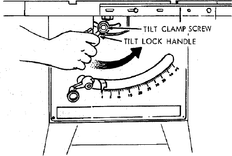
- Rotate tilt crank CLOCKWISE a few turns to tilt blade. Now rotate crank COUNTERCLOCKWISE until it stops. Blade should now be square with table and pointer should point to “O”.
If blade IS SQUARE to table;
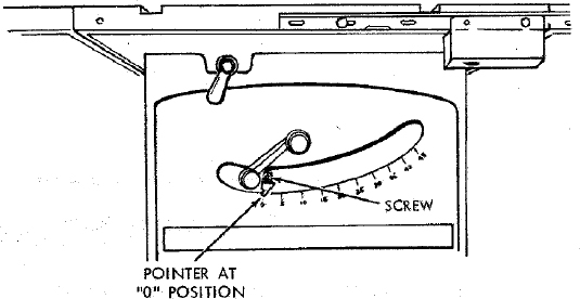
- Check pointer
If POINTER DOES NOT point to the “O” mark on the bevel scale;
- Loosen screw and adjust pointer … using medium screwdriver.
If blade is NOT SQUARE to table … the 90° LIMIT STOP must be ADJUSTED.
Using a medium size screwdriver, loosen BOTH setscrews in 90° STOP COLLAR.
NOTE: If you can’t reach the setscrews, turn the TILT CRANK slightly.
ROTATE the STOP COLLAR moving it all the way to the end of TILT SCREW. (to the right)
TILT blade RIGHT or LEFT … checking with your square until blade is square to table.
ROTATE STOP COLLAR moving it to the right until it stops … TIGHTEN the setscrews.
Check POINTER. If it DOES NOT point to the “O” mark on the bevel scale … loosen screw and adjust pointer.
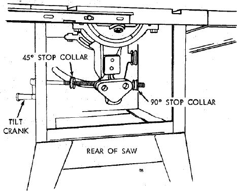
45° POSITION
TILT blade to LEFT as far as it will go. It will stop when the PIVOT NUT is against the 45° STOP COLLAR … and the pointer SHOULD POINT to the “45” mark on the bevel scale.
If POINTER DOES NOT POINT to the “45” mark … the 45° STOP COLLAR must be ADJUSTED.
Insert a medium screwdriver through the slot and loosen BOTH setscrews in 45° STOP COLLAR.
NOTE: If you can’t reach the setscrews, turn the TILT crank slightly.
Reach inside the saw from REAR … ROTATE the STOP COLLAR a few turns moving it toward the TILT CRANK (to the left).
TILT blade until POINTER points to “45” mark.
ROTATE STOP COLLAR moving it to the right until it stops … TIGHTEN the setscrews.
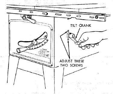
TILT MECHANISM
The crank should turn freely without binding. The turning action can be adjusted by tightening or loosening the screws in the bearing retainer.
NOTE: When adjusting the screws on the tilt crank, hold the nut inside using a 3/8 in. wrench.
MAINTENANCE
WARNING: FOR YOUR OWN SAFETY, TURN SWITCH “OFF” AND REMOVE PLUG FROM POWER SOURCE OUTLET BEFORE MAINTAINING OR LUBRICATING YOUR SAW.
Do not allow sawdust to accumulate inside the saw.
Frequently blow out any dust that may accumulate inside the saw cabinet and the motor.
Frequently clean your cutting tools with Craftsman Gum and Pitch Remover.
A coat of automobile-type wax applied to the table will help to keep the surface clean and allow workplaces to slide more freely. Treat unplated and unpainted steel parts and surfaces with Sears “Stop Rust.”
If the power cord is worn or cut, or damaged in any way, have it replaced immediately.
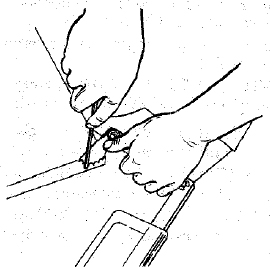
Make sure the teeth of the ANTIKICKBACK pawls are always sharp. To sharpen:
- Remove blade guard.
- Rotate pawl toward rear of spreader so that teeth are above top of spreader.
- Hold spreader with left hand and place pawl over corner of workbench.
- Using a small round file (Smooth Cut) sharpen the teeth.
LUBRICATION
The following parts should be oiled occasionally with SAE No. 20 or No. 30 engine oil.
- Tilt screw threads and pivot nut. (First Clean with Craftsman Gum & Pitch Remover.)
- Elevation screw threads and pivot nut. (First Clean with Craftsman Gum & Pitch Remover.)
- Cradle bearing points.
- Bearing points in guard assembly, miter gauge and rip fence.
* BEARING POINTS
RECOMMENDED ACCESSORIES
IN CANADA, SEE YOUR LOCAL SIMPSONS-SEARS STORE OR CATALOG FOR ACCESSORY SELECTION AND NUMBERS.
| ITEM | CAT. NO. |
|---|---|
| Steel Legs | 9-22235 |
| Steel Stand | 9-22214 |
| Tool Bench | 9-1071 |
| Retractable Caster Set for Steel Legs | 9-22209 |
| Retractable Caster Set for Steel Stand | 9-22201 |
| Solid Table Extension | 9-29957 |
| * Adjustable Table Extension | 9-2178 |
| 7 In. Molding Head Set | 9-3217 |
| 7 In. Molding Head Set | 9-3218 |
| 7 In. Molding Head | 9-3214 |
| Molding/Dado Insert for 7 In, Dia. Molding or Dado Head | 9-29994 |
| Work Light | 9-2480 |
| Work Light | 9-2481 |
| 7 In. Dia. Adjustable Dado Head | 9-3263 |
| 7 In. Dia. Dado Head | 9-3257 |
| Blade Stabilizers | 9-4952 |
| Sanding Wheel | 9-22723 |
| Miter-Gauge Stop Rods | 9-29924 |
| Miter-Gauge Hold-Down Clamp | 9-29928 |
| Hold-Down Set | 9-3230 |
| Taper Jig | 9-3233 |
| Universal Jig | 9-3231 |
| Power Tool Know How Handbooks Table Saw | 9-2918 |
*CAN ONLY BE ATTACHED TO SAW TABLE NOT TO TABLE EXTENSIONS.
TROUBLE SHOOTING
WARNING: FOR YOUR OWN SAFETY, TURN SWITCH “OFF” AND ALWAYS REMOVE PLUG FROM POWER SOURCE OUTLET BEFORE TROUBLESHOOTING.
TROUBLE SHOOTING -- GENERAL
| TROUBLE | PROBABLE CAUSE | REMEDY |
|---|---|---|
| Excessive vibration. | 1. Blade out of balance. | 1. Discard Blade and use a different blade. |
| Cannot make square Cut when crosscutting. | 1. Miter gauge not adjusted properly. | 1. See “Adjustments” section “Miter Gauge.” |
| Cut binds, burns or stalls motor when ripping. | 1. Dull blade with improper tooth set. | 1. Sharpen or replace blade. |
| 2. Blade is Heeling. | 2. See “Adjustments” section, “Heeling Adjustment…” | |
| 3. Make sure concave or hollow side is facing “down,” feed slowly. | 3. Warped board. | |
| 4. Rip fence not parallel to blade. | 4. See “Assembly” section, “Aligning Rip Fence” | |
| 5. Spreader out of alignment | 5. See “Assembly” section, “Installing Blade Guard.” | |
| Cut not true at 90° or 45° positions. | 1. Stop collars not properly adjusted. | 1. See “Adjustments” section, “Blade Tilt, or “Squareness of Blade to Table.” |
| Tilt crank and elevating crank turn hard. | 1. Sawdust on threads of tilt screw or elevating screw. | 1. See “Maintenance and Lubrication” section. |
| 2. Bearing retainers to tight. | 2. See “Maintenance” section “Tilt and Elevation Mechanism.” |
TROUBLE SHOOTING -- MOTOR
NOTE: Motors used on wood-working tools are particularly susceptible to the accumulation of sawdust and wood chips and should be blown out or “vacuumed” frequently to prevent interference with normal motor ventilation.
| TROUBLE | PROBABLE CAUSE | REMEDY |
|---|---|---|
| Excessive noise. | 1. Motor. | 1. Have motor checked by qualified service technician. Repair service is available at your nearest Sears store. |
| Motor fails to develop full power. (Power output of motor decreases rapidly with decrease in voltage at motor terminals. For example, a reduction of 10% in voltage causes a reduction of 19% in maximum power output of which the motor is capable, while a reduction of 20% in voltage causes a reduction of 36% in maximum power output.) | 1. Circuit overloaded with lights, appliances and other motors. | 1. Do not use other appliances or motors on same circuit when using the saw. |
| 2. Undersize wires or circuit too long. | 2. Increase wire sizes, or reduce length of wiring. See “Motor Specification and Electrical Requirements” section. | |
| 3. General overloading of power company facilities. (In some sections of the country, demand for electrical power may exceed the capacity of existing generating and distribution systems.) | 3. Request a voltage check from the power company. | |
| 4. Incorrect fuses or circuit breakers in power line. | 4. Install correct fuses or circuit breakers. | |
| Motor starts slowly or fails to come up to full speed. | 1. Low voltage will not trip relay. | 1. Request voltage check from the power company. |
| 2. Windings burned out or open. | 2. Have motor repaired or replaced. | |
| 3. Starting relay not operating. | 3. Have relay replaced. | |
| Motor overheats. | 1. Motor overloaded. | 1. Feed work slower into blade. |
| 2. Improper cooling. (Air circulation restricted through motor due to sawdust, accumulating inside of saw). | 2. Clean out sawdust to provide normal air circulation through motor. See “Maintenance and Lubrication” section. | |
| Starting switch in motor will not operate. | 1. Burned switch contacts (due to extended hold-in periods caused by low line voltage, etc.) | 1. Have switch replaced and request a voltage check from the power company. |
| 2. Shorted capacitor (when equipped) | 2. Test capacitor and replace if defective. | |
| 3. Loose or broken connections. | 3. Have wiring checked and repaired. | |
| Motor stalls (resulting in blown fuses or tripped circuit breakers). | 1. Starting switch not operating. | 1. Have switch replaced. |
| 2. Voltage too low to permit motor to reach operating speed. | 2. Request voltage check from the power company. | |
| 3. Fuses or circuit breakers do not have sufficient capacity. | 3. Install proper size fuses or circuit breakers. | |
| Frequent opening of fuses or circuit breakers. | 1. Motor overloaded. | 1. Feed work slower into blade. |
| 2. Fuses or circuit breakers do not have sufficient capacity. | 2. Install proper size fuses or circuit breakers. | |
| 3. Starting switch not operating (motor does not reach speed). | 3. Have switch replaced. |
REPAIR PARTS
PARTS LIST FOR CRAFTSMAN 10 INCH TABLE SAW MODEL NO. 113.299142, 113.299040 & 113.298470
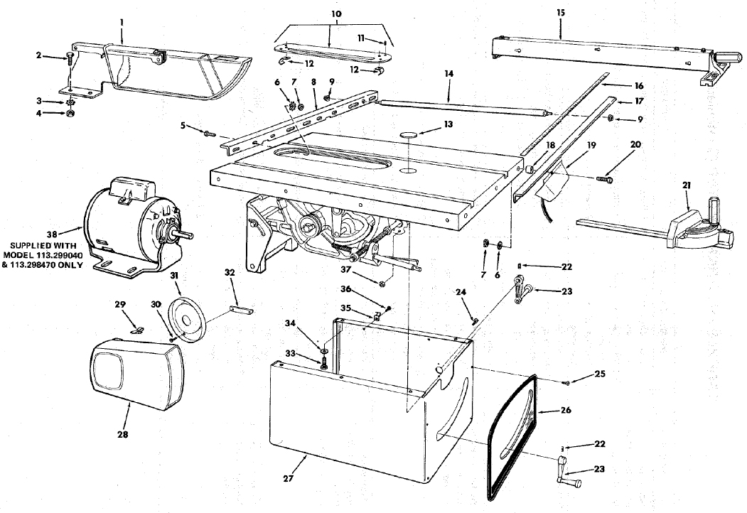
Figure 1
Always order by Part Number – not by Key Number.
FIGURE 1 PARTS LIST
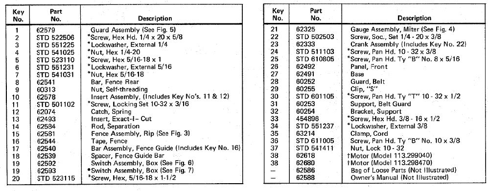
* Standard Hardware Item – May Be Purchased Locally.
NOTE: Shipping and handling charges for standard hardware items (identified by *) such as nuts, screws, washers, etc., make buying these items by mail uneconomical. To avoid shipping and handling charges, you may obtain most of these locally.
•Supplied in Canada Only.
†Stock Item – May be secured through the hardware department of most Sears or Simpsons-Sears Retail Stores or Catalog Order Houses.
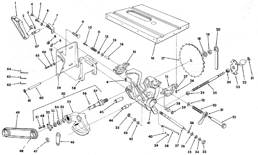
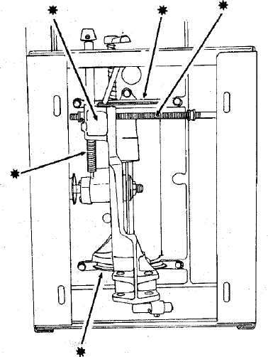
Figure 2
FIGURE 2 PARTS LIST
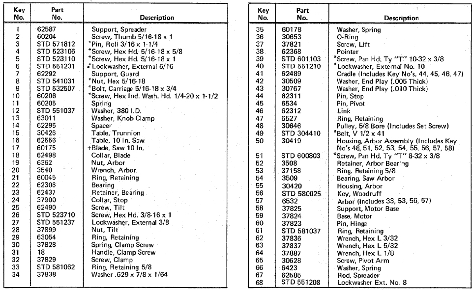
* Standard Hardware Item - May Be Purchased Locally.
+ Stock Item – May be secured through the Hardware Department of most Sears or Simpsons-Sears Retail Stores or Catalog Order Houses.
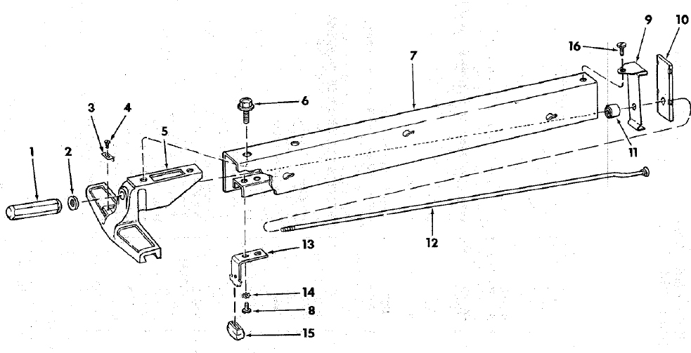
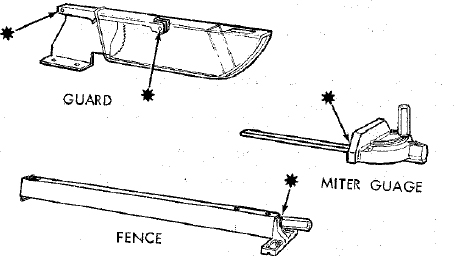
FIGURE 3 - 62581 FENCE ASSEMBLY
| Key No. | Part No. | Description |
|---|---|---|
| – | 62581 | Fence Assembly, Rip |
| 1 | 62524 | Handle |
| 2 | STD 551031 | *Washer, 21/64 I.D. |
| 3 | 62534 | Indicator, Fence |
| 4 | 60049 | *Screw, Pan Hd. Type “T” 4-40 × 3/16 |
| 5 | 62527 | Head, Fence |
| 6 | 423350 | Screw, Sems 3/8-16 × 1/2 |
| 7 | 62582 | Channel, Fence |
| 8 | STD 611005 | *Screw, Pan Hd. Type “A” 10-32 × 5/8 |
| 9 | 62528 | Spring, Fence Lock |
| 10 | 62529 | Lock, Rear Fence |
| 11 | 62531 | Roller, Rear Fence |
| 12 | 62583 | Rod, Fence Lock |
| 13 | 62533 | Spring, Head Alignment |
| 14 | STD 551210 | *Lockwasher, External No. 10 |
| 15 | 62532 | Pad, Aliqnment |
| 16 | STD 600805 | *Screw, Pan Hd. Type “T” 8-32 × 1/2 |
* Standard Hardware Item – May be Purchased Locally.
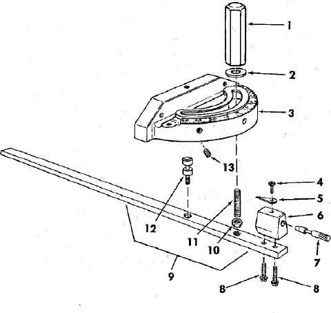
FIGURE 4 - 62325 MITER GUAGE ASSEMBLY
| Key No. | Part No. | Description |
|---|---|---|
| – | 62325 | †Gauge Assembly, Miter |
| 1 | 62524 | Handle, Miter Gauge |
| 2 | STD 551031 | *Washer, Plain, 21/64 × 1 × 1/16” |
| 3 | 37893 | Gauge, Miter |
| 4 | STD 600803 | *Screw, Pan Hd. 8-32 × 5/16” |
| 5 | 135 | Indicator |
| 6 | 37895 | Block, Miter Gauge Indicator |
| 7 | 37896 | Pin, Miter Gauge Stop |
| 8 | 9417295 | *Screw, Pan Hd., w/Lockwasher, 8-32 × 5/8”. |
| 9 | 62230 | Rod Assembly, Miter Gauge, Consisting of Items 10, 11, 12 |
| 10 | STD 541231 | *Nut, Hex., 5/16-18 × 1/2 × 3/16” |
| 11 | 62225 | Stud, Clamp |
| 12 | 62383 | Stud, Pivot |
| 13 | STD 502503 | Screw, Set 1/4-20 × 3/8” |
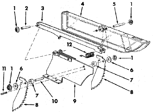
FIGURE 5 - 62579 GUARD ASSEMBLY
| Key No. | Part No. | Description |
|---|---|---|
| 62579 | Guard Assembly, Saw | |
| 1 | 60297 | Nut, Push |
| 2 | 62391 | Pin 1/4 × 1-1/2” |
| 3 | 62395 | Support, Guard |
| 4 | 62389 | Guard, Saw |
| 5 | 62390 | Pin, 1/4 × 1-3/4” |
| 6 | STD 551025 | * Washer, 17/64 × 5/8 × 1/16” |
| 7 | 62136 | Spacer, Pawl |
| 8 | 62396 | Pawl |
| 9 | 62580 | Spreader, Assembly Blade |
| 10 | 62410 | Pin, 1/4 × 1” |
| 11 | STD 571810 | *Pin, Roll, 3/16 × 15/16” |
| 12 | 62134 | Spring, Pawl |
* Standard Hardware Item – May be Purchased Locally.
†Stock Item – May be secured through the Hardware Departments of most Sears or Simpsons-Sears Retail Stores or Catalog Order Houses.
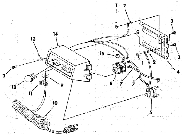
FIGURE 6 - 62592 SWITCH BOX ASSEMBLY (DOMESTIC)
| Key No. | Part No. | Description |
|---|---|---|
| – | 62592 | Switch Box Assembly |
| 1 | STD 541110 | *Nut Hex., 10 - 32 |
| 2 | STD 551210 | *Lockwasher, 10, Int. Tooth |
| 3 | STD 601103 | *Screw, Pan Hd. 10 - 32 × 3/8 |
| 4 | 62466 | Bracket, Housing |
| 5 | 62679 | Outlet |
| 7 | 62486 | Lead w/OC Terminals |
| 8 | 60267 | Switch, Locking |
| 9 | 60290 | Washer |
| 10 | 62484 | Cord with Plug |
| 11 | 61086 | Relief, Strain |
| 12 | 60256 | Key, Switch |
| 13 | 60287 | *Screw, Nylon Pan Hd., 6 - 32 × 5/16 |
| 14 | 62483 | Box, Switch |
| 15 | 63467 | Insulator, Cap Flag Terminal. |
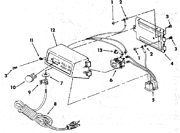
FIGURE 7 - 62593 SWITCH BOX ASSEMBLY (SUPPLIED IN CANADA ONLY)
| Key No. | Part No. | Description |
|---|---|---|
| – | 62593 | Switch Box Assembly |
| 1 | STD 541110 | *Nut, Hex., 10-32 |
| 2 | STD 551210 | *Lockwasher/10 Internal Tooth |
| 3 | STD 601103 | *Screw, Pan Hd., 10-32 × 3/8 |
| 4 | 62466 | Bracket, Housing |
| 5 | 62376 | Outlet |
| 6 | 60267 | Switch, Locking |
| 7 | 60317 | Washer |
| 8 | 60271 | Cord with Plug |
| 9 | 62503 | Relief, Strain |
| 10 | 60256 | Key, Switch |
| 11 | STD 510603 | *Screw, Pan Hd., 6-32 × 3/8 |
| 12 | 62502 | Box, Switch |
| 13 | 63467 | Insulator, Cap Flag Terminal |
* Standard Hardware Item – May Be Purchased Locally.
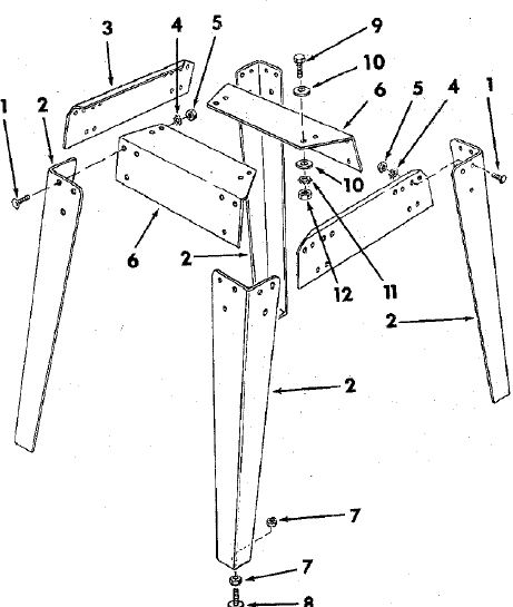
FIGURE 8 - LEGS FOR MODEL 113.299040 AND 113.298470 ONLY
NOT SUPPLIED IN CANADA
| Key No. | Part No. | Description |
|---|---|---|
| 1 | 60314 | Screw, Serrated Truss Hd. 1/4-20 × 5/8 |
| 2 | 62552 | Leg |
| 3 | 62554 | Stiffener, Side |
| 4 | STD 551225 | *Lockwasher, Ext. 1/4 |
| 5 | STD 541025 | *Nut, Hex 1/4-20 |
| 6 | 62553 | Stiffener, End |
| 7 | 120238 | Nut, Hex 1/2-13 |
| 8 | 803835 | Foot, Leveling |
| HARDWARE FOR ATTACHING LEGS TO SAW. | ||
| 9 | STD 523112 | *Screw, Hex Hd. 5/16-18 × 1-1/4 |
| 10 | STD 551031 | Washer, 11/32 I.D. |
| 11 | STD 551131 | *Lockwasher, Ext. 5/16 |
| 12 | STD 541031 | *Nut, Hex 5/16-18 |
| 62591 | •Bag of Loose Parts (not illustrated) |
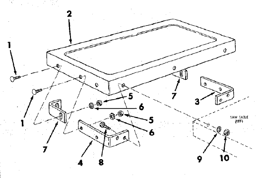
FIGURE 9 - TABLE EXTENSION FOR MODEL 113.299040 AND 113.298470 ONLY
| Key No. | Part No. | Description |
|---|---|---|
| – | 62589 | †Extension Assembly, Complete |
| 1 | 60323 | Screw, Serrated Truss Hd., 1/4-20 × 1” |
| 2 | 62590 | Extension |
| 3 | 62549 | Bracket, Corner Support No. 2 |
| 4 | 62548 | Bracket, Corner Support No. 1 |
| 5 | STD 541025 | *Nut, Hex 1/4-20 |
| 6 | STD 551225 | *Lockwasher, Ext. 1/4 |
| 7 | 62550 | Bracket, Corner Stiffener |
| HARDWARE FOR ATTACHING EXTENSION TO TABLE. | ||
| 8 | STD 523112 | *Screw, Hex Hd. 5/16-18 × 1-1/4 |
| 9 | STD 551131 | *Lockwasher, Ext. 5/16 |
| 10 | STD 541031 | *Nut, Hex 5/16-18 |
| 62591 | •Bag of Loose Parts (not illustrated) |
* Standard Hardware Items - May be Purchased Locally.
• Bag contains all Loose Parts for both Legs and Extensions.
†Stock Item - May be secured through the Hardware Departments of most Sears or Simpsons-Sears retail stores or catalog order house.
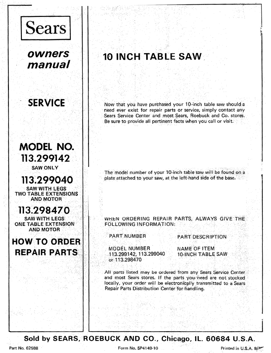
Parts & More
Elliptical Machine
Exercise Cycle
Front-Engine Lawn Tractor
Gas Chainsaw
Gas Walk-Behind Mower
Ice Cream Maker
Microwave/Hood Combo
Power Saw
Range
Rear-Engine Riding Mower
Refrigerator
Side-By-Side Refrigerator
Small Appliance
Toaster Oven