- Kenmore refrigerator water filters
- Whirlpool refrigerator water filters
- Samsung refrigerator water filters
- GE refrigerator water filters
- LG refrigerator water filters
- Frigidaire refrigerator water filters
- KitchenAid refrigerator water filters
- Maytag refrigerator water filters
- Kenmore Elite refrigerator water filters
- Estate refrigerator water filters
- GE Profile refrigerator water filters
- Amana refrigerator water filters
- Bosch refrigerator water filters
- Dacor refrigerator water filters
- Electrolux refrigerator water filters
Top DIY repair help
View All Repair Categories
Appliances
Lawn & Garden
Power Tools
Home Improvement
Sports & Leisure
Heating & Cooling
Quick Links
How to replace a snowblower 4-way chute control assembly
less than a minute readFeb 18Lyle Weischwill
Repair time and Difficulty
30 minutes or less
Tools Required
- Socket set and ratchet
- Ratchet extension
- Needle-nose pliers
- Work gloves
This snowblower repair guide gives instructions for replacing a 4-way chute control assembly, which includes the joystick, chute rod and chute control gearbox. The joystick turns the chute rod, which connects to the snowblower chute control gearbox. The chute control gearbox pivots the chute when you move the joystick. If the chute won't turn, replace the chute control assembly with a manufacturer-approved snowblower part.
Use these steps to replace the 4-way chute control assembly on common Craftsman and MTD snowblowers.
Instructions
- 1. Disconnect the trigger cable
Remove the 3 screws from the joystick handle and separate the handle halves.
Disconnect the trigger cable and set the joystick handle, trigger and cable slide receiver aside.
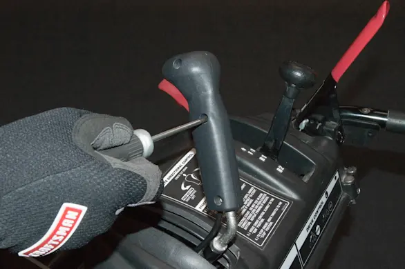
PHOTO: Remove the screws. 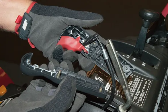
PHOTO: Separate the handle.
- 2. Disconnect the chute deflector control cables
Remove the nut and slide the mounting bolt out of the chute deflector cable bracket.
Remove the tilt guide mounting screw from the inside of the chute.
Pivot the cable bracket out and disengage the locking tabs from the deflector.
Squeeze the cable locking tabs with pliers and pull the cables out of the cable bracket.
Disconnect the 2 cables from the tilt guide.
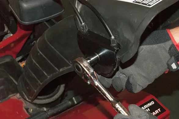
PHOTO: Remove the mounting bolt. 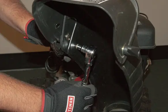
PHOTO: Remove the tilt guide screw. 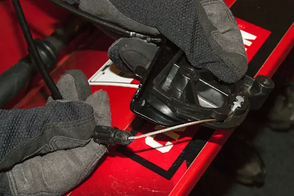
PHOTO: Release the cable locking tabs. 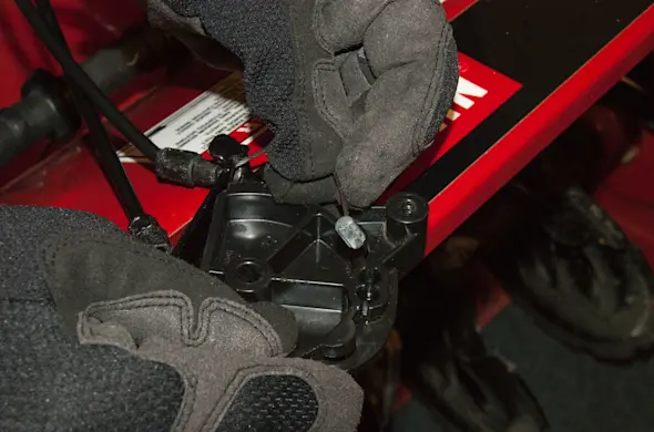
PHOTO: Disconnect the cables.
- 3. Remove the 4-way control assembly
Remove the bow tie cotter pin from the chute control shaft and slide the shaft out of the 4-way chute control.
Remove the 6 mounting screws and then remove the 4-way control assembly.
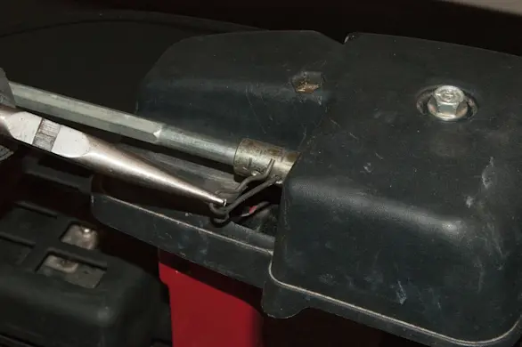
PHOTO: Remove the cotter pin from the chute control shaft. 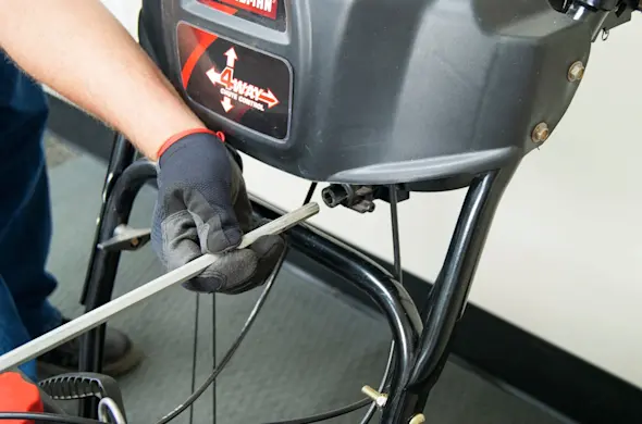
PHOTO: Release the control rod. 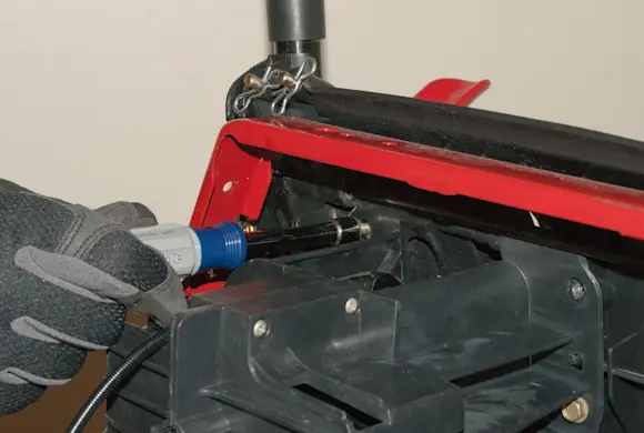
PHOTO: Remove the screws. 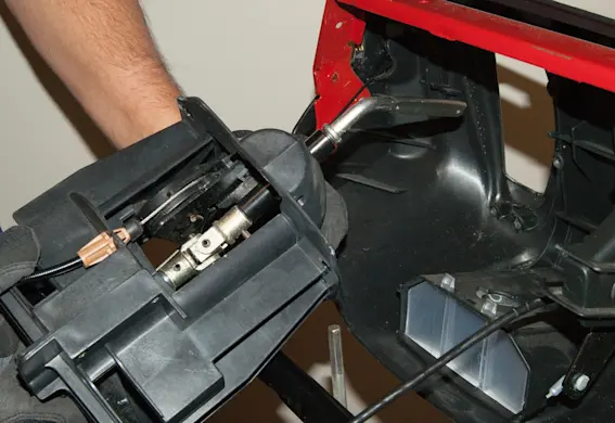
PHOTO: Remove the 4-way control.
- 4. Install the new 4-way control assembly
Route the trigger cable through the oval opening and up through the joystick rod opening on the new 4-way control assembly.
Route the deflector control cables behind the handle and mount the new 4-way control assembly to the control panel using the mounting screws.
Center the trigger on the control panel and position the chute facing straight ahead to align the trigger control.
Reconnect the chute control shaft to the 4-way control assembly and then reinstall the bow tie cotter pin to secure the chute control shaft.
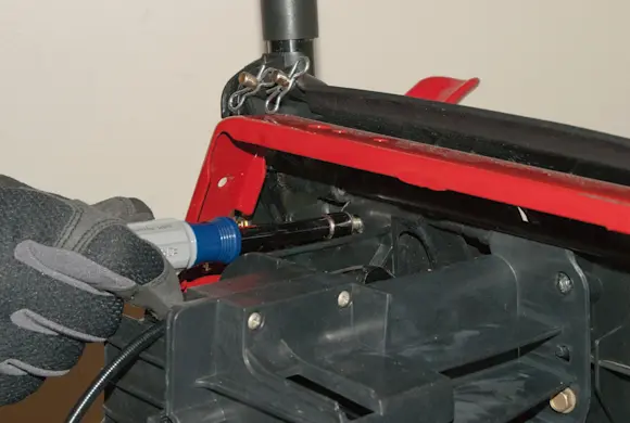
PHOTO: Install the new 4-way control. 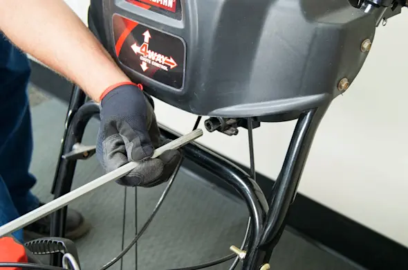
PHOTO: Reinstall the control rod. 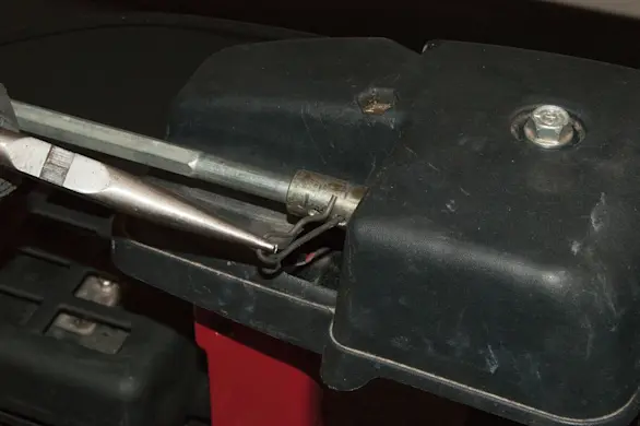
PHOTO: Reinstall the cotter pin.
- 5. Connect the deflector cables
Route the chute control cables through the cable bracket on the muffler shroud.
Route the front chute control cable coming out of the 4-way control assembly into the rear cable mount on the tilt guide.
Route the rear chute control cable into the front cable mount on the tilt guide.
Insert the two cable bracket tabs into the slots on the deflector.
Position the tilt guide under the cable bracket and insert the cable locking tabs into the cable bracket.
Reinstall the mounting bolt through the cable bracket and secure it using the mounting nut.
Reinstall the mounting screw to secure the tilt guide to the deflector.
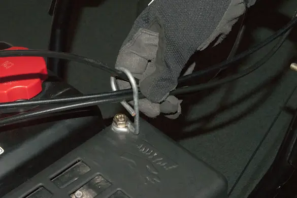
PHOTO: Route the cables through the bracket. 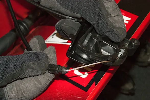
PHOTO: Connect the cable to the tilt guide. 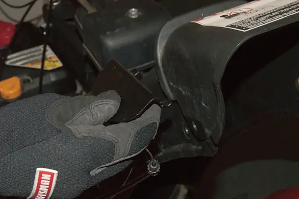
PHOTO: Connect the bracket. 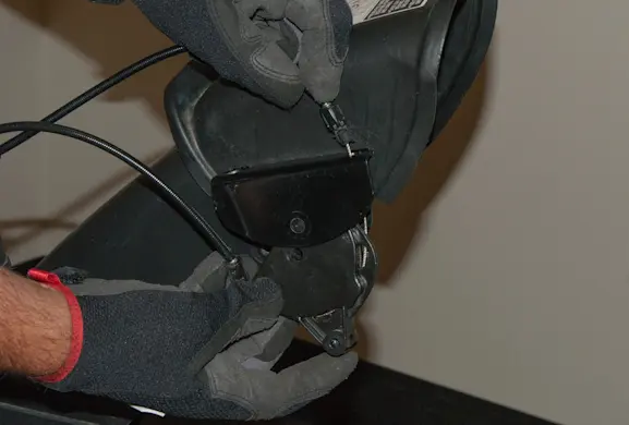
PHOTO: Connect the cables to the bracket. 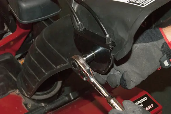
PHOTO: Reinstall the mounting bolt. 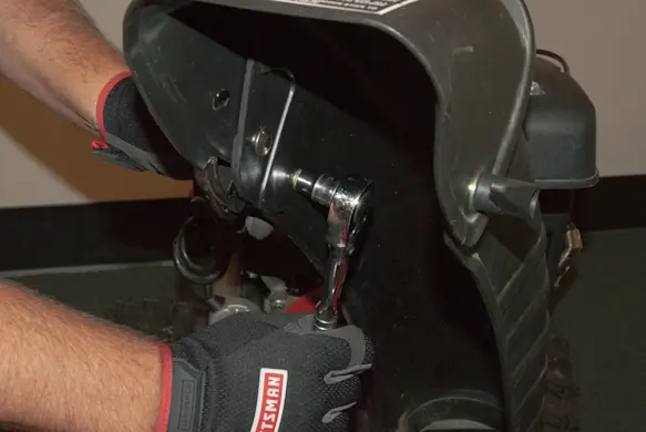
PHOTO: Reinstall the tilt guide screw.
- 6. Reconnect the trigger cable
Position the end of the cable in the cable slide receiver.
Place the cable slide in the right half of the trigger handle with the slot and cable ball facing the trigger.
Reinstall the trigger in the pivot hole on the right half of the trigger handle and slip the trigger tab into the cable slide receiver slot.
Insert the cable sleeve end into the bracket on the right half of the trigger handle.
Reinstall the left half of the trigger handle onto the right half of the trigger handle and slide the trigger handle onto the trigger shaft while holding the two halves together.
Reinstall the trigger mounting screws.
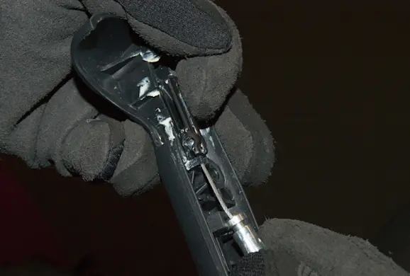
PHOTO: Position the cable in the handle. 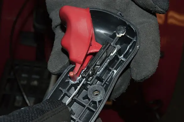
PHOTO: Reinstall the trigger. 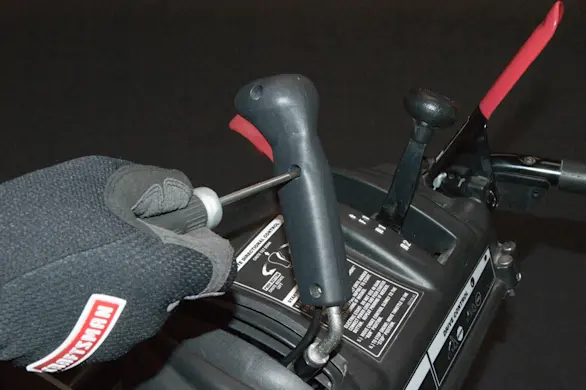
PHOTO: Reinstall the screws.